
close
Choose Your Site
Global
Social Media

Views: 0 Author: Site Editor Publish Time: 2026-07-04 Origin: Site


Achieving precise motion control often creates a frustrating engineering dilemma. You need tight positioning accuracy but cannot always justify the prohibitive cost and complexity of a full servo system. Standard 2-phase steppers frequently fall short in demanding industrial environments. They inherently suffer from disruptive mid-band resonance and severe high-speed torque drop-off. These limitations restrict throughput and compromise operational smoothness. A 3 Phase Stepper Motor offers a compelling strategic middle ground. It bridges the gap perfectly for automation, CNC machining, and high-speed continuous motion applications.
This technology delivers smoother rotation and sustained power across wider speed ranges. Our guide objectively evaluates the technical advantages, practical implementation realities, and overall commercial viability of adopting 3-phase stepper technology. You will discover exactly how this unique magnetic design upgrades physical resolution. We will also show you how to properly match drives and manage mechanical retrofitting considerations. Proper implementation ensures maximum machine performance and system reliability.
Precision Upgrade: A standard 1.2° stepper motor inherently offers 50% higher baseline resolution than standard 1.8° 2-phase equivalents before microstepping is even applied.
Vibration Reduction: 3-phase technology significantly mitigates mid-frequency resonance, ensuring smoother operation and lower acoustic noise.
Torque at Speed: 3-phase motors maintain a flatter torque curve at higher RPMs, bridging the performance gap between basic steppers and expensive BLDC servos.
Integration Readiness: Standardized footprints (e.g., NEMA23 / 57mm) allow for straightforward mechanical drop-in, though drive architectures must be updated.
Traditional 2-phase steppers exhibit well-documented physical limitations. Low-speed torque ripple creates noticeable mechanical jitter during slow movements. Mid-band resonance often induces unexpected stalling when the motor passes through critical frequencies. Furthermore, as speeds increase, 2-phase motors experience rapid torque degradation. The magnetic core cannot magnetize and demagnetize fast enough to maintain rotational force. These inherent flaws force engineers into over-sizing motors just to guarantee sufficient high-speed power.
Dividing the magnetic field across three distinct phases drastically smooths power delivery. The overlapping phase currents eliminate the torque dead spots common in 2-phase designs. When one phase begins to lose magnetic pull, the next phase has already established a strong magnetic field. This continuous overlapping action stabilizes the rotor. It translates directly into fluid, continuous motion even at challenging speeds.
The mechanical advantage of a 1.2° stepper motor design is immense. It provides 300 physical steps per revolution instead of the standard 200. This configuration reduces dependency on extreme microstepping algorithms to achieve physical positioning accuracy. Physical pole alignment always provides stiffer, more accurate holding torque than electrically interpolated microsteps. You gain a higher baseline resolution before the drive even applies digital smoothing.
Thermal efficiency also sees notable improvements. Three-phase stators distribute electrical current more evenly across the motor windings. This distribution prevents localized hot spots. Measurable reductions in heat generation occur during high-duty-cycle operations. Industry-standard thermal dissipation tests show that these motors run cooler under identical load conditions. Cooler operation directly extends bearing life and protects internal winding insulation.
Technical Metric | Standard 2-Phase Motor | 3-Phase Motor Architecture |
|---|---|---|
Step Angle | 1.8° (200 steps/rev) | 1.2° (300 steps/rev) |
Mid-Band Resonance | High susceptibility to stalling | Naturally dampened, highly stable |
High-Speed Torque | Drops sharply above 600 RPM | Maintains flatter curve past 1000 RPM |
Power Delivery | Pronounced torque ripple | Smooth, overlapping magnetic flux |
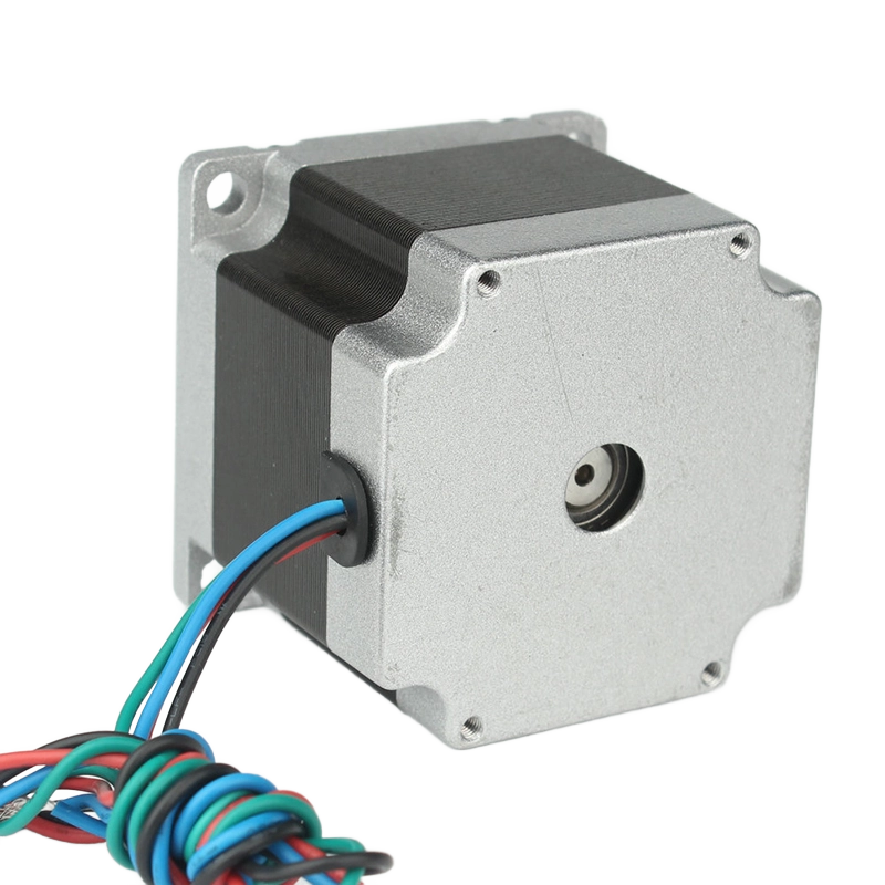
Mechanical integration dictates how easily new technology fits into existing assembly lines. The NEMA23 3Phase motor serves as the baseline standard for medium-payload industrial applications. It offers a perfect balance of compact sizing and substantial power output. Standardization ensures that engineers can upgrade legacy systems without redesigning expensive mounting brackets. You simply swap the physical motor hardware while retaining your existing mechanical layout.
Assessing the 57mm 3Phase stepper motor reveals millimeter-exact equivalents designed for global supply chain procurement. The 57mm designation strictly matches the NEMA23 standard. Frame length variations provide crucial scalability. Lengths typically range from 54mm up to 76mm. These physical dimensions share a direct correlation to holding torque. A shorter 54mm frame might output 0.9 Nm, while a robust 76mm frame pushes beyond 2.0 Nm. You can scale your power requirements precisely without altering the faceplate footprint.
Migrating from a legacy 2-phase setup requires careful mechanical retrofitting considerations. Shaft diameters represent the most common stumbling block. Check whether your existing system uses a 6.35mm (1/4 inch) or an 8mm shaft. Mounting hole configurations generally align perfectly, but bolt depths may vary slightly based on flange thickness. Flexible coupling compatibility is another vital factor. You must ensure the inner diameter of your current couplers perfectly grips the new motor shaft to prevent backlash.
Shaft Sizing: Verify exact shaft diameter and check for D-cut flats or keyways.
Coupling Integrity: Inspect existing jaw or bellows couplings for wear before attaching the new motor.
Clearance Depth: Measure the rear clearance space, as higher-torque models feature longer body lengths.
Thermal Contact: Ensure the mounting face maintains good contact with a thermally conductive metal chassis for optimal cooling.
Engineers frequently encounter a common misconception regarding microstepping. Many believe microstepping infinitely increases absolute mechanical accuracy. This assumption is false. Microstepping primarily increases operational smoothness. It divides the electrical current to create intermediate steps between physical rotor poles. However, friction, load inertia, and minor manufacturing tolerances prevent the motor from achieving perfect absolute accuracy at extreme microstep resolutions. You cannot expect a heavily loaded motor to settle perfectly on a 1/256th microstep.
A 3-phase architecture exhibits incredible synergy with modern digital control logic. When paired with advanced DSP-based digital drives, the motor operates with exceptional fluidity. The drive calculates precise current vectors for all three phases simultaneously. It generates perfectly synchronized overlapping sine waves. This clean electrical delivery prevents the sharp magnetic jerks that typically cause audible whining and mechanical vibration in older systems.
Understanding vibration dampening requires looking at the physics of resonance. Every motor acts like a mass-spring system. The rotor mass interacts with the magnetic "spring" of the stator. Standard 2-phase motors naturally resonate heavily in the 100-200 Hz band. If you run the motor at speeds generating step frequencies in this band, the motor often stalls violently. Three-phase systems naturally suppress this exact resonance band. The third phase constantly stabilizes the rotor. You can confidently command the motor to accelerate through critical speed zones without fear of stalling.
Calculate Real Load: Always measure the actual friction and inertia before relying on microsteps for final positioning.
Optimize Resolution: Set drive microstepping between 1000 and 2000 pulses per revolution for the best balance of smoothness and processing speed.
Enable Digital Smoothing: Activate internal anti-resonance features on DSP drives to further refine the overlapping sine waves.
Profile Acceleration: Use S-curve acceleration ramps in your controller to prevent sudden jerk loads during rapid speed changes.
Making smart engineering choices requires a balanced financial evaluation. The core components demand higher upfront investment. You can expect a 3-phase motor and its required dedicated drive to cost 20–40% more than a basic 2-phase equivalent. This premium covers the complex winding architecture and the sophisticated H-bridge electronics inside the driver. You must weigh this initial layout against the operational gains in speed and reliability.
You must outline exact success criteria when deciding to overrule 2-phase options. Certain scenarios make the upgrade mandatory. If your application requires sustained operation above 1000 RPM, 2-phase motors will likely fail or drop steps. Strict low-noise requirements in laboratory or medical settings also demand 3-phase smoothness. Furthermore, applications like automated optical inspection require absolute stability. Camera triggers fail if the motor jitters upon settling. Three-phase technology eliminates that settling jitter almost entirely.
You also need to know when to stop short of full servo systems. Three-phase steppers act as the definitive alternative to servos when closed-loop dynamic load adjustments are not strictly required. Servos require complex PID loop tuning, expensive high-resolution encoders, and premium drives. If your load remains relatively constant and predictable, a high-speed stepper handles the job perfectly. You avoid the immense tuning complexity and expense of a servo architecture while still achieving high-speed, continuous motion.
Application Requirement | Recommended Technology | Key Procurement Rationale |
|---|---|---|
Basic low-speed positioning | Standard 2-Phase Stepper | Lowest upfront cost, simple integration |
High-speed continuous motion (>1000 RPM) | 3-Phase Stepper | Maintains torque, prevents stalling, budget-friendly |
Acoustically sensitive environments | 3-Phase Stepper | Suppressed resonance yields low-decibel operation |
Dynamic, unpredictable load shifting | Full AC/DC Servo System | Requires closed-loop feedback for instant correction |
Successful deployment heavily relies on understanding the drive dependency. You absolutely cannot run a 3-phase motor on a standard 2-phase driver. They are physically and electrically incompatible. A 2-phase driver utilizes two independent H-bridges to power four output wires. A 3-phase system requires a dedicated drive capable of managing three intersecting phases. Selecting a perfectly matched 3-phase driver is non-negotiable. Using mismatched equipment guarantees immediate system failure and potential hardware damage.
Wiring and pinout complexity present common implementation pitfalls. These motors typically utilize either 3-wire (U, V, W) or 6-wire configurations. Incorrect phase sequencing is a widespread error during installation. If you swap two phase wires inadvertently, the motor will exhibit erratic stepping behavior. It may vibrate loudly without turning, or it may experience complete directional failure. You must carefully consult the manufacturer datasheet. Verify color codes rigorously before applying power to the drive terminals.
Power supply sizing directly dictates high-speed capabilities. You need concrete strategies for matching bus voltage to your performance targets. A 24VDC supply works adequately for low-speed, high-torque applications. However, high speeds require much higher voltage. We recommend moving to a 48VDC or higher supply for applications demanding rapid RPMs. Higher voltage directly overcomes the back-electromotive force (back-EMF) generated by the spinning rotor. If the supply voltage cannot push past this back-EMF, phase current drops sharply. The motor will lose torque and eventually stall.
Upgrading to 3-phase stepper motors delivers tremendous strategic value for modern automation. They effectively bridge the gap between basic open-loop motion control and high-end servo systems. You gain significantly smoother rotation, vastly reduced mid-band resonance, and excellent torque retention at higher speeds. This technology allows machines to run faster and quieter without the programming headaches of servo loops.
Use a simple shortlisting heuristic for your next project. First, verify your exact holding and dynamic torque requirements. Second, confirm that the mechanical footprint aligns with standard NEMA23/57mm mounting dimensions to minimize redesigns. Finally, always select a perfectly matched, dedicated 3-phase drive system to unlock the motor's full potential.
Take action on your design upgrades today. Consult manufacturer technical datasheets to verify electrical specifications. Download a reliable motor sizing calculator to analyze your specific application parameters. If you encounter complex load inertia ratios, contact an application engineer immediately to ensure your selected components guarantee flawless machine execution.
A: A 1.2° motor produces 300 steps per revolution, whereas a 1.8° motor produces 200 steps. This structural difference yields 50% finer baseline mechanical resolution. You achieve smoother low-speed tracking and higher physical accuracy without relying solely on the drive's digital microstepping interpolation.
A: No. The internal H-bridge architecture is fundamentally different. A 3-phase motor requires a dedicated drive capable of generating three intersecting, overlapping sine waves. Connecting it to a 2-phase drive will result in immediate operational failure and possible hardware damage.
A: It offers superior holding torque at zero speed. It locks into position securely without wandering. It also lacks complex tuning requirements, offers predictable open-loop positioning, and keeps total system costs significantly lower than a full brushless DC servo setup.
A: It heavily mitigates mid-band resonance compared to standard 2-phase designs. The overlapping magnetic phases stabilize the rotor. However, precise DSP drive tuning and appropriate physical dampening mechanisms remain essential best practices to achieve optimal acoustic performance and absolute smoothness.


