close
Choose Your Site
Global
Social Media
Views: 0 Author: Site Editor Publish Time: 2026-09-15 Origin: Site
Precision motion control is the foundational requirement for any successful automated system. A single missed step can ruin hours of machining or printing. Selecting an underpowered or mismatched motor leads to resonance issues, thermal throttling, skipped steps, and catastrophic hardware failure. Over-speccing wastes budget and adds unnecessary weight and inertia to the moving axes. To build reliable machines, engineers must establish a technical framework for evaluating torque curves, frame sizes, and driver compatibility. This process ensures you specify the exact Stepper Motor required for specific mechanical loads without compromising speed or accuracy. By understanding the physical limitations and electrical characteristics of these systems, you can optimize motion setups for maximum efficiency.
Application Dictates Size: NEMA 17 is the standard for 3D printing due to its low mass, while CNC and industrial automation require the higher holding torque of NEMA 23, NEMA 24, or NEMA 34.
Torque vs. Speed Trade-off: Stepper motors inherently lose torque at higher RPMs; evaluating the pull-out torque curve is more critical than looking solely at static holding torque.
Inductance Matters: Lower inductance motors allow for faster current saturation, enabling higher speeds without losing steps, provided the power supply and driver can handle the current.
Closed-Loop Adoption: For mission-critical CNC and automation tasks, closed-loop stepper systems offer a reliable middle ground between traditional open-loop steppers and expensive servo motors.
Holding torque represents the force required to move the rotor when the motor is powered but stationary. While manufacturers advertise this prominently, pull-out torque is the actual metric you need for dynamic applications. Pull-out torque defines the usable force during motion. You must read the manufacturer's torque curve to understand how rapidly force diminishes as RPM increases. If you only look at holding torque, your machine will stall during rapid travel moves.
Step angle directly impacts mechanical resolution. Standard motors utilize a 1.8-degree step angle, yielding 200 steps per revolution. High-resolution 0.9-degree motors provide 400 steps per revolution. Microstepping through the driver increases smoothness and reduces resonance. However, it does not linearly increase mechanical accuracy or dynamic torque. Relying on microstepping for precision under heavy loads often leads to positional errors because the incremental torque between microsteps is extremely low.
Phase configurations dictate operational smoothness. Standard 2-phase motors dominate the market due to simplicity and low driver cost. Conversely, 3-phase designs exhibit lower step angle error, reduced mid-band resonance, and smoother operation. The trade-off involves increased driver complexity and wiring requirements. For high-end automation, 3-phase systems provide a noticeable upgrade in surface finish for machined parts.
Matching rotor inertia to load inertia prevents stalling. Mid-band resonance occurs when the step frequency aligns with the mechanical natural frequency of the system. This causes severe vibration and lost steps. You can mitigate this through mechanical dampening, adjusting acceleration profiles, or utilizing advanced DSP drivers with anti-resonance algorithms. A mismatched inertia ratio (greater than 10:1) guarantees poor performance.
Voltage and inductance ratios determine high-speed viability. The formula for maximum optimal voltage is 32 multiplied by the square root of the motor's inductance. Pairing a high-inductance motor with a low-voltage power supply severely limits high-speed performance. The current simply cannot saturate the coils fast enough during rapid stepping. Always match your power supply to the calculated optimal voltage.
Driver technology dictates current control and acoustic output. Traditional chopper drivers offer robust performance but generate audible noise. Advanced drivers, such as the TMC2209 or TMC5160, provide Silent Step Stick capabilities. StealthChop modes offer near-silent operation but reduce torque at high speeds. SpreadCycle modes maximize torque output while generating slightly higher audible noise. You must configure the driver based on whether you prioritize silence or raw power.
Motor Inductance (mH) | Calculated Optimal Voltage (V) | Recommended Power Supply |
|---|---|---|
1.5 | 39.1 | 36V or 48V |
2.8 | 53.5 | 48V or 60V |
4.0 | 64.0 | 60V or 72V |
6.5 | 81.5 | 80V |
Extrusion systems demand specific motor characteristics. Direct Drive extruders require lightweight pancake designs. A low-mass 3D printer stepper motor reduces X-axis artifacting and ringing. The reduced mass minimizes momentum during rapid direction changes, improving print quality. Bowden setups, conversely, require higher torque to push filament through a long PTFE tube. This necessitates a larger motor mounted off the moving gantry.
The NEMA 17 form factor is the undisputed standard for 3D printer X, Y, and Z axes. It balances physical footprint, weight, and sufficient torque. Typical holding torque ranges from 40 to 60 N·cm. This size provides enough force to move lightweight carriages rapidly without introducing excessive inertia into the mechanical system.
Deploying 0.9-degree high-resolution motors on the X and Y gantry improves fine detail reproduction. Using them on the extruder prevents extrusion pulsing artifacts, ensuring consistent filament flow. Standard 1.8-degree motors remain ideal for the Z-axis. The Z-axis requires maximum holding torque to support the mass of the gantry or build plate, especially on larger format printers.
Thermal management is critical in enclosed builds. Standard motors utilize Class B insulation, rated for moderate temperatures. High-temperature enclosures used for ABS or PC printing require Class H insulation. Motor heat transferring to plastic mounts causes warping. Heat creeping into the extruder softens filament prematurely, leading to severe jams and failed prints.
Identify the moving mass of your X and Y axes.
Select a motor weight that keeps total carriage mass under your target limit.
Verify the torque curve supports your desired print speeds (e.g., 150mm/s+).
Check the insulation class if building a heated chamber.
The CNC environment presents high-resistance cutting forces. Chip load and material hardness dictate the required torque. NEMA 23, NEMA 24, and NEMA 34 are the industry standards for these applications. A robust CNC machine motor ensures the cutter maintains position against the resistance of wood, plastic, or metal. Undersized motors will stall, ruining the workpiece and potentially breaking the endmill.
Mechanical transmission compatibility dictates motor selection. Lead screws provide high mechanical advantage but low speed. Ball screws offer high efficiency and precision. Rack-and-pinion systems require high dynamic torque for rapid feed rates over long distances. The motor must scale with the torque multipliers and speed requirements of the chosen drive mechanism. You cannot use the same motor for a 1605 ball screw and a direct-drive rack system.
Closed-loop hybrid systems integrate encoders to monitor shaft position. In CNC machining, closed-loop steppers prevent ruined workpieces by correcting minor positional errors dynamically. If steps are unrecoverably lost due to a severe crash or overload, the drive faults out. This stops the machine immediately before further damage occurs to the spindle or the fixture.
Axis-specific requirements vary significantly. A Z-axis requires high holding torque or an integrated electromagnetic brake. This prevents the heavy spindle from dropping into the table when unpowered. The X and Y axes require high dynamic torque to maintain rapid feed rates during complex toolpaths. You often need larger motors on the Y-axis if it drives a heavy gantry.
Environmental protection ensures longevity. CNC routing and milling generate wood dust, aluminum chips, and liquid coolants. Sourcing dust-proof and water-resistant IP65-rated motors is essential for industrial use cases. Standard open-frame motors will ingest conductive chips or coolant, leading to internal short circuits and premature bearing failure.
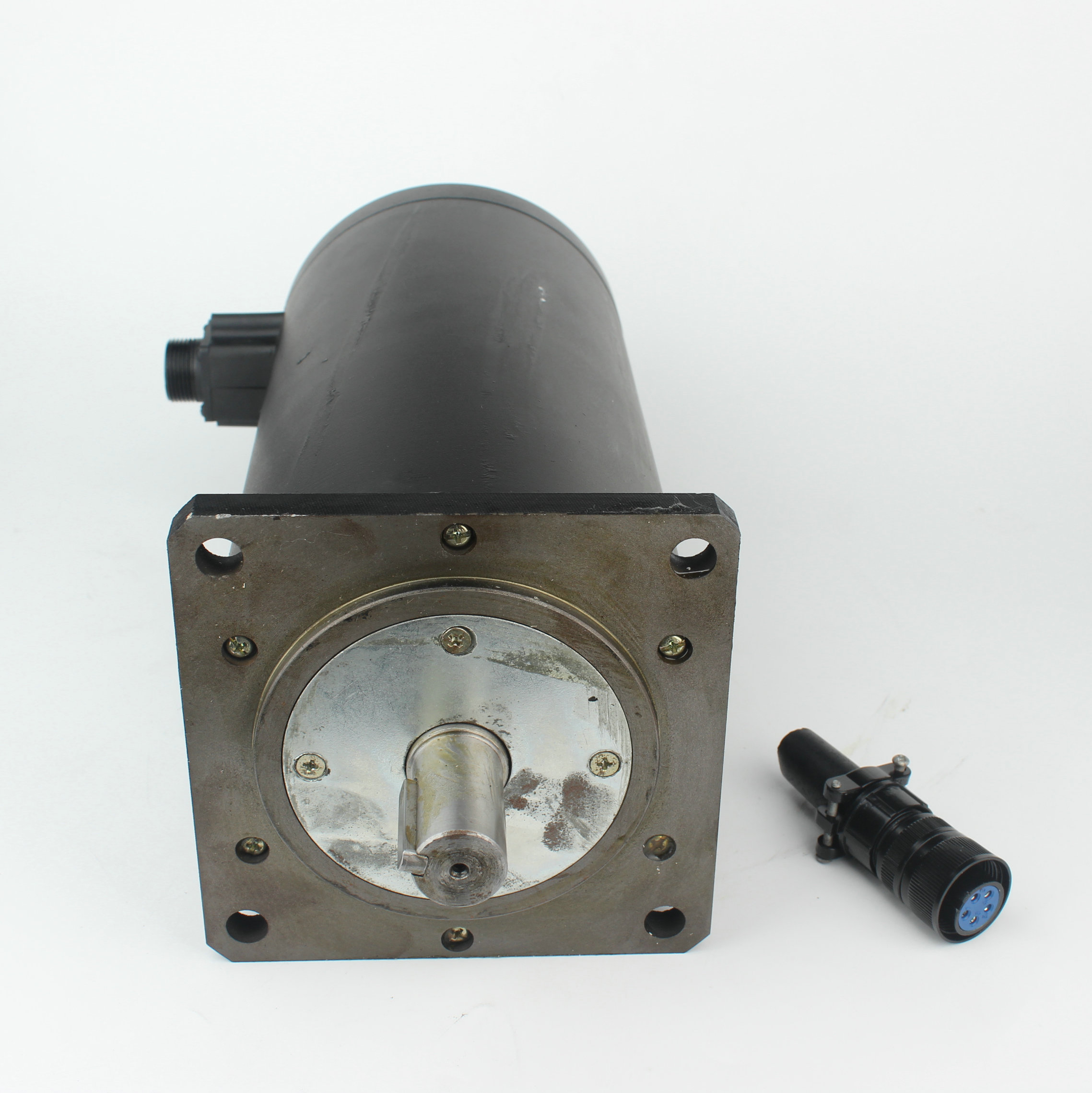
The NEMA24 DC stepper motor bridges the gap between NEMA 23 and NEMA 34. It serves as the optimal solution for automation engineers needing more torque than a NEMA 23 can provide. It fits perfectly when you lack the physical space to accommodate a bulky NEMA 34 frame on a conveyor or robotic arm.
Mechanical upgrades of the NEMA 24 standard include a 60mm flange, compared to the 57mm flange of a NEMA 23. Thicker shaft options, typically 8mm or 10mm, handle higher shear loads and radial forces. The larger stator and rotor assembly allows for better thermal dissipation under continuous load. This makes it highly reliable for repetitive pick-and-place operations.
Integration with PLCs and motion controllers requires careful planning. Motors interface with industrial control systems via dedicated drivers. Robust, optically isolated drivers protect sensitive PLC and logic circuits. They block high-voltage spikes and electromagnetic noise generated by the motor coils from feeding back into the control cabinet.
Duty cycle and continuous operation impact longevity in 24/7 automation environments. Bearing life degrades under continuous radial loads from tight belts. Heat dissipation strategies, such as active cooling or aluminum mounting plates, are necessary. Implementing automated current-reduction at idle prevents overheating when the motor is simply holding position between cycles.
Feature | NEMA 23 | NEMA 24 | NEMA 34 |
|---|---|---|---|
Flange Size | 57mm | 60mm | 86mm |
Typical Shaft Diameter | 6.35mm / 8mm | 8mm / 10mm | 12.7mm / 14mm |
Max Holding Torque | ~3.0 N·m | ~4.0 N·m | ~12.0 N·m |
Space Requirement | Compact | Moderate | Large |
Cost-to-performance ratios heavily favor steppers for low-speed applications. Steppers offer high torque at low speeds for a fraction of the cost of servo systems. Servos dominate high-speed, high-precision, dynamic load applications. If your machine requires continuous torque across a wide RPM range, servos are mandatory. If you need cheap, reliable holding power, steppers win.
High-speed torque drop-off is a physical reality for stepper systems. Avoid using steppers for applications requiring high RPMs, such as spindles or rapid transit over long distances. The inductance of the coils prevents rapid current changes. This causes torque to plummet as speed increases. Servos maintain a flat torque curve up to their rated RPM.
Complexity of implementation differs drastically. Open-loop steppers offer plug-and-play simplicity. You wire the coils, set the current, and send step pulses. Servo motors require complex PID tuning, precise encoder wiring, and continuous feedback loop monitoring to function correctly. Poorly tuned servos will oscillate and vibrate violently.
Preventing skipped steps requires systematic troubleshooting. The primary culprits of lost steps include aggressive acceleration profiles, mechanical binding in the linear rails, and under-specced power supplies. Verify mechanical smoothness by pushing the axes by hand before adjusting electrical parameters. If the mechanics bind, no amount of motor current will fix the issue.
Managing Back Electromotive Force protects the electronics. Rapid deceleration or manually moving axes generates Back EMF. This acts as a generator, sending high voltage back into the circuit. This voltage spike can easily destroy stepper drivers. Utilize flyback diodes, braking resistors, or transient voltage suppressors to absorb this energy safely.
Wiring, shielding, and EMI management ensure reliable signals. Use shielded, twisted-pair cables for all motor wiring. In CNC environments with high-frequency VFD spindles, electromagnetic interference causes false steps. Ground the shielding at one end only to prevent ground loops. Route high-voltage AC lines far away from low-voltage DC step and direction signals.
Use shielded cables for all motor runs.
Ground the shield at the control cabinet star ground.
Separate AC and DC wiring in the cable chains.
Install braking resistors on large NEMA 34 systems.
Calculate your required dynamic torque and load inertia to establish a baseline requirement before purchasing hardware.
Select the smallest NEMA frame that meets the torque requirement to minimize moving mass and reduce system resonance.
Match the motor's inductance with an appropriate high-voltage power supply and DSP driver to ensure high-speed reliability.
Prototype the motion system using conservative acceleration values to verify stability before pushing the machine to its limits.
A: Bipolar motors use 4 wires and energize the entire coil, offering higher torque density. Unipolar motors use 6 or 8 wires with a center tap, energizing only half the coil at a time. Bipolar is preferred for modern CNC and 3D printing due to superior performance and simpler driver integration.
A: For hobbyist or prosumer wood-cutting machines, NEMA 23 motors with holding torque between 120 and 300 oz-in (0.85 to 2.1 N·m) are typically required. This provides enough force to handle the cutting loads of routing hardwood or aluminum without losing steps during aggressive toolpaths.
A: While possible for very light engraving or diode laser cutting, NEMA 17 motors lack the dynamic torque required for routing wood or milling metal. They will stall under the resistance of heavy cutting tools, resulting in ruined workpieces and broken endmills.
A: Stepper motors lose steps when the physical load exceeds the motor's available torque. This is caused by resonance vibrations, inadequate driver current, mechanical binding in the rails, or attempting to accelerate the mass too rapidly for the motor's capability.
A: The power supply voltage should be based on the motor's inductance rating. For a NEMA 24, this typically ranges from 36V to 48V DC. Higher voltage overcomes coil inductance faster, ensuring optimal high-speed performance and preventing torque drop-off at higher RPMs.
A: They do not magically increase physical torque to prevent a stall. However, they detect the stall via an encoder, attempt to push maximum current to correct the positional error, and fault out safely if the position cannot be recovered, saving the workpiece.