close
Choose Your Site
Global
Social Media
Views: 0 Author: Site Editor Publish Time: 2026-09-24 Origin: Site
Modern automation and motion control systems face a strict engineering challenge: achieving high torque output and precision within tightly confined spatial footprints. Specifying the wrong motor and gearbox combination carries heavy risks. Under-speccing components leads to premature mechanical failure, stripped gears, and extensive downtime. Over-speccing inflates the bill of materials and adds unnecessary weight to the final assembly, degrading dynamic performance. The planetary gear system stands as the industry standard for maximizing torque density while maintaining strict coaxial alignment. Proper specification requires a deep understanding of mechanical principles, standard frame sizes, and technical selection criteria for industrial applications.
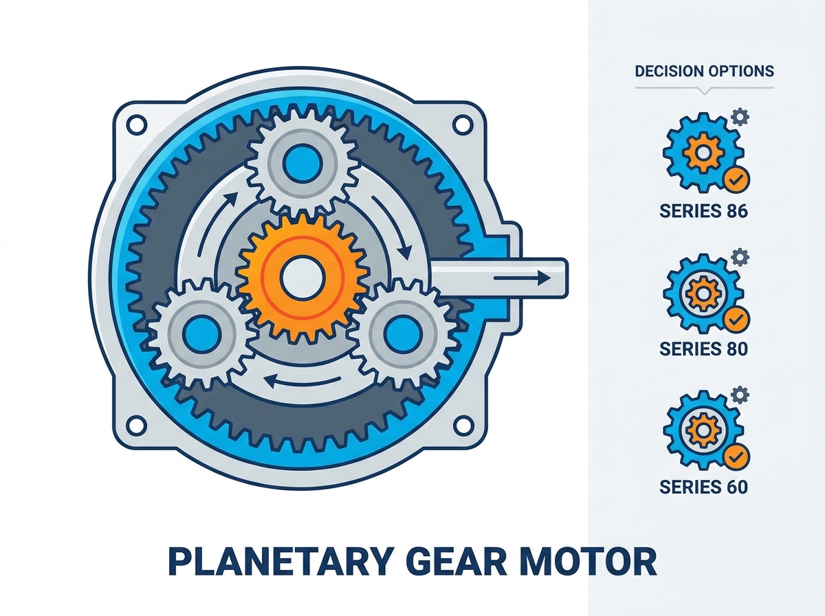
Mechanical Efficiency: Planetary gear motors utilize an epicyclic design (sun, planet/satellite, and ring gears) to distribute loads across multiple contact points, enabling higher torque transmission than parallel-axis designs.
Form Factor vs. Output: The coaxial alignment of the motor and gearbox provides a compact footprint, ideal for space-constrained applications like AGVs, robotics, and aerospace mechanisms.
Standardized Sizing: Selecting the correct frame size—such as a series 60 gear motor, series 80 gear motor, or series 86 gear motor—dictates radial load capacity, continuous torque, and thermal dissipation limits.
A planetary system relies on three primary mechanical elements working in unison. The sun gear sits at the absolute center of the mechanism. This central input is typically driven directly by the motor shaft. Manufacturers either cut the sun gear directly into the motor shaft or attach it via a rigid collet to prevent slippage under heavy loads. Surrounding the sun gear are the planet gears, also known as satellites. These gears mesh continuously with the sun gear and distribute the mechanical load evenly across multiple points. A rigid planet carrier holds these satellites in place. The carrier ensures they maintain proper spacing as they rotate and acts as the primary output mechanism. Finally, a stationary outer ring gear, or annulus, encloses the entire assembly. The ring gear features internal teeth that mesh with the outer edges of the planet gears. This outer ring dictates the rotational output and contains the internal separating forces generated during operation. Engineers typically specify hardened steel alloys for these components, utilizing processes like carburizing or nitriding to increase surface hardness while maintaining a ductile core to absorb shock.
The kinematics of this epicyclic system are highly efficient. As the motor turns the central sun gear, the planet gears are forced to orbit around it. They simultaneously rotate on their own individual axes while rolling along the stationary internal teeth of the ring gear. This shared load distribution is the secret to high torque capacity. Because multiple gear teeth engage at the exact same time, the physical stress on any individual tooth drops significantly. This prevents tooth shearing under heavy dynamic loads or sudden stops. It also acts as a highly effective mechanical speed reducer. You achieve massive torque multiplication without increasing the physical diameter of the gear housing. The forces cancel each other out radially, which protects the motor shaft bearings from excessive side loading. Engineers often specify these systems when shock loads would otherwise destroy standard parallel-axis gearboxes. The balanced internal forces mean the output shaft runs exceptionally true, minimizing runout and vibration at the load connection point.
A single-stage planetary gearbox typically offers reduction ratios ranging from 3:1 up to 10:1. Physical geometry limits this ratio. Making the sun gear too small weakens it, while making the ring gear too large defeats the purpose of a compact footprint. If you require higher torque or much lower output speeds, you must stack multiple stages together. In a multi-stage configuration, the output carrier of the first stage acts directly as the input sun gear for the second stage. This modular stacking allows you to achieve exponentially higher reduction ratios. Ratios can easily exceed 1000:1 in a three- or four-stage setup. However, adding stages increases the physical length of the gearbox. It also introduces slight mechanical efficiency drops due to the added friction of more moving components and gear meshes. Each additional stage typically reduces overall mechanical efficiency by roughly 3 to 5 percent, which must be factored into the initial motor sizing calculations.
Configuration | Typical Ratio Range | Efficiency per Stage | Physical Length Impact | Best Use Case |
|---|---|---|---|---|
Single-Stage | 3:1 to 10:1 | ~97% | Shortest | High-speed, moderate torque applications |
Two-Stage | 12:1 to 100:1 | ~94% | Moderate | Standard industrial automation and AGVs |
Three-Stage | 120:1 to 1000:1 | ~90% | Long | Heavy lifting, extreme torque multiplication |
Planetary designs pack serious mechanical power into a very small package. They offer significantly higher torque density per cubic inch compared to traditional helical or parallel-shaft spur gearboxes. This high torque-to-weight ratio makes them ideal for mobile robotics, automated guided vehicles (AGVs), and aerospace applications. You can effectively downsize the overall motor package without sacrificing output power. This weight reduction improves the dynamic response of the machine. Less mass means lower inertia, allowing for faster acceleration and deceleration profiles in automated machinery. When designing a robotic arm, placing a lighter gearhead at the joint reduces the overhung load, which directly improves the positioning accuracy of the entire system. The power density allows engineers to meet strict weight budgets in battery-operated vehicles without compromising on the tractive effort required to move heavy payloads.
The input shaft and the output shaft share the exact same rotational axis. This coaxial alignment provides a massive spatial advantage for mechanical engineers. It enhances concentricity and improves overall system precision. Machine design becomes much simpler when you do not have to account for offset shafts or bulky side-mounted gearboxes. The symmetrical, cylindrical footprint fits easily into tubular housings. This is particularly useful for pipe inspection robots, inline actuators, and power tools where radial space is strictly limited. The inline design also simplifies mounting brackets and reduces the overall footprint of the machine chassis. You can slide the entire motor and gearbox assembly into a tight cylindrical sleeve without worrying about asymmetrical clearance issues. This symmetry also aids in balancing rotating assemblies, reducing the need for complex counterweights in high-speed applications.
Thermal management is a critical reality in these tightly packed systems. The high friction generated by multiple simultaneous gear meshes produces significant heat. While planetary systems are mechanically efficient, this compact heat generation can become problematic during continuous duty cycles. Continuous operation at peak loads requires careful attention to cooling. You must consider specific lubrication types, such as high-temperature synthetic greases or oil baths. In extreme cases, active cooling mechanisms or external heat sinks are necessary to prevent thermal breakdown of the seals and lubricants. When the internal temperature exceeds the rating of the shaft seals, the elastomer degrades, leading to fluid leaks and eventual catastrophic failure of the gear mesh.
To manage heat effectively, engineers employ several strategies:
Selecting synthetic lubricants with higher thermal breakdown thresholds.
Mounting the gearbox to a large aluminum machine frame to act as a natural heat sink.
Programming the motion controller to include brief dwell times, allowing the internal components to shed heat.
Upgrading to a larger frame size to increase the physical thermal mass of the gearbox housing.
Utilizing finned motor housings to increase the surface area available for convective cooling.
Spur gears rely entirely on single-point contact. All the mechanical force transfers through one or two teeth at any given moment. Planetary gears utilize multi-point contact through their satellite arrangement. This fundamental difference gives the planetary design superior structural rigidity. They handle high radial and axial loads much better than spur alternatives. When sudden shock loads occur, the planetary system absorbs the impact across multiple satellites. This prevents catastrophic tooth failure. The robust output carrier also supports heavier overhung loads on the output shaft, allowing you to mount pulleys or sprockets directly without external bearing supports. High-quality planetary units often feature angular contact bearings on the output shaft, which specifically manage the heavy axial thrust loads generated by helical gears or external lead screws.
Backlash is the slight physical clearance between mating gear teeth. In standard parallel spur configurations, backlash can be significant and unpredictable. Planetary systems naturally offer lower backlash ratings, often measured in just a few arc-minutes. Low-backlash precision is mandatory for specific motion tasks. CNC positioning systems, robotic joints, and surgical robotics require exact repeatability. A precision planetary setup eliminates the mechanical slop that ruins positioning accuracy. When a robotic arm reverses direction, low backlash ensures the end-effector moves exactly as commanded without a delayed response. Standard planetary units might have 15 arc-minutes of backlash, while precision-ground units can achieve sub-3 arc-minute ratings. This tight tolerance requires exceptional machining capabilities, including skiving and precision grinding of the internal ring gear.
Manufacturing a planetary system requires tight tolerances and complex machining techniques like internal broaching for the ring gear. They carry a manufacturing premium over simple spur designs. However, the return on investment becomes clear when evaluating lifecycle and reliability. If your application demands high cycle rates, heavy loads, and strict precision, the upfront investment pays off rapidly. You eliminate frequent gear replacements and costly machine downtime. For low-torque, continuous-run applications like simple fans or pumps, a spur gear might suffice. But for dynamic motion control, the planetary design is unmatched. The extended operational lifespan in high-stress environments easily justifies the initial specification of a planetary unit over a cheaper parallel-axis alternative.
Feature | Planetary Gearbox | Spur Gearbox |
|---|---|---|
Load Distribution | Multi-point contact (shared load) | Single-point contact (concentrated load) |
Torque Density | Very High | Low to Moderate |
Backlash | Low (Precision options available) | High (Prone to mechanical slop) |
Radial Load Capacity | Excellent (Supported by carrier bearings) | Poor (Requires external support) |
Shaft Alignment | Coaxial (Inline) | Parallel (Offset) |
Noise Profile | Moderate (Complex mesh frequencies) | High (Distinct gear whine at speed) |
A series 60 gear motor features a compact 60mm square or cylindrical frame. It delivers reliable continuous torque for smaller, precision-focused applications. These units are perfect for light-duty automation, packaging mechanisms, and medical devices. Precision instrumentation also benefits heavily from this size where space is at an absolute premium. They provide enough mechanical advantage to drive small belts and lead screws without adding unnecessary bulk to the machine frame. The 60mm size typically utilizes a smaller shaft diameter, making it suitable for lower radial load requirements. Engineers often pair this frame size with NEMA 23 or 400W servo motors to create a highly responsive, compact actuator. The mounting flanges usually conform to standard metric patterns, allowing for easy integration into existing aluminum extrusion frameworks.
Stepping up to a series 80 gear motor provides excellent mid-range capabilities. The 80mm frame handles significantly higher radial loads and offers better thermal mass for heat dissipation. You will frequently see these integrated into material handling equipment, sorting conveyors, and automated warehouse systems. Medium-payload robotics also rely on the 80mm size for smooth, consistent joint actuation. This frame size strikes an optimal balance between physical footprint and heavy-duty torque output, making it a highly versatile choice for general industrial automation. The larger bearings inside the 80mm frame allow for direct mounting of heavier drive wheels in mobile robot applications. Shaft options typically expand at this size, offering keyed, flat, or splined configurations to handle the increased torque transfer without slipping.
For heavy-duty industrial tasks, the series 86 gear motor is the standard workhorse. This 86mm frame often aligns directly with NEMA 34 motor mounting standards. It excels in applications requiring massive, sustained torque output. Heavy AGV drivetrains, industrial extruders, and large-scale CNC machinery depend on this robust footprint. The larger internal gears and oversized output bearings easily handle punishing industrial environments. When shock loads are frequent and continuous duty is required, the 86mm frame provides the necessary structural integrity to prevent mechanical failure. The thick ring gear housing resists deformation even under extreme torsional strain. Engineers specify this size when the application involves moving heavy castings, driving large indexing tables, or operating heavy-duty winches where failure is not an option.
Proper mechanical sizing always starts with precise math. You must determine the continuous torque (Root Mean Square or RMS) and the peak or stall torque requirements of your specific load. Never size a motor based solely on peak torque, or you risk severe overheating during continuous operation. Next, calculate the necessary gear reduction ratio. Divide the base motor’s optimal operating RPM by your required final output speed. This specific ratio ensures the motor runs constantly in its most efficient power band. You must also calculate load inertia and match it closely to the motor's rotor inertia. A severe mismatch here causes tuning instability and erratic motion profiles. The gear ratio plays a massive role in inertia matching; the reflected load inertia decreases by the square of the gear ratio, making a planetary gearbox an excellent tool for controlling highly inertial loads.
Follow this standard workflow for sizing:
Calculate the maximum load torque required during the acceleration phase.
Determine the continuous RMS torque required during the constant velocity phase.
Select a gear ratio that allows the motor to operate near its rated speed.
Verify that the reflected load inertia falls within an acceptable ratio to the motor rotor inertia (typically under 10:1).
Apply a service factor (Ka) multiplier based on the application's shock load profile (e.g., 1.0 for uniform loads, 1.5 for heavy shock).
Check the manufacturer's radial and axial load limits for the selected output shaft.
The planetary gearhead is only half the equation. You must pair it with the correct motor technology. Brushless DC (BLDC) motors offer excellent longevity, zero brush maintenance, and high-speed performance. Stepper motors are ideal for exact, repeatable positioning tasks without needing complex encoder feedback. Brushed DC motors work well for cost-sensitive, simple control systems where precision is secondary. You must also decide between integrated and modular configurations. A factory-assembled gear motor saves installation time and guarantees alignment. A modular setup allows you to replace just the motor or gearbox if one component fails, which simplifies field maintenance. Modular setups require careful attention during assembly to ensure the motor pinion aligns perfectly with the planetary satellites, avoiding premature wear from angular misalignment.
Your machine's duty cycle dictates internal material selection. Intermittent operations with long cooling periods might allow for powdered metal or even high-grade polymer gears. Continuous, heavy-duty cycles absolutely demand hardened, precision-machined steel gears. Environmental factors also play a massive role in selection. Look closely at IP ratings to ensure proper sealing against dust, debris, and moisture. Washdown environments in food processing require IP67 or IP69K ratings. Harsh environments dictate whether you use standard grease or specialized synthetic oil lubrication to keep the internal components protected from premature wear. If the unit operates in sub-zero temperatures, you must specify low-temperature grease to prevent the lubrication from solidifying and causing gear lockup. Conversely, high-ambient temperature environments require Viton seals to prevent the elastomers from baking and cracking over time.
Planetary systems can be inherently noisy. The multiple simultaneous gear meshes generate more sound and vibration than a simple helical setup, especially at high input speeds. You can actively mitigate this acoustic noise during the design phase. Specifying helical planetary gears instead of straight spur planetary gears reduces vibration significantly by allowing teeth to engage gradually. Utilizing sound-dampening enclosures around the machine chassis helps contain the noise. You can also adjust the motor drive profile in the software to smooth out harsh accelerations, which prevents gear clatter. Proper alignment of the motor shaft to the sun gear is also critical; any angular misalignment will amplify vibration through the entire assembly. Engineers often use flexible couplings in modular setups to absorb minor misalignments and dampen high-frequency vibrations before they reach the machine frame.
Thermal failure is a very real risk in confined spaces. Multi-stage gearboxes running at high input speeds generate substantial internal heat. If the heat cannot escape, the lubrication breaks down, leading to rapid metal-on-metal wear. You can prevent this through proper duty-cycle programming, ensuring the motor has time to cool. Adding aluminum heat sinks to the mounting flange helps dissipate thermal energy away from the gearbox. Sometimes, selecting a larger frame size is the best engineering solution. Moving from a 60mm to an 80mm frame increases the thermal mass, allowing the system to run much cooler under the exact same load. Monitoring the casing temperature with external sensors can also provide early warning signs of thermal overload, allowing the control system to throttle back performance before permanent damage occurs.
Mounting orientation matters significantly for gearbox longevity. If you mount the unit vertically with the output shaft pointing straight up, gravity pulls the internal lubrication away from the primary gear mesh. This causes immediate starvation and rapid wear on the upper bearings and gears. To avoid this, specify sealed-for-life units designed specifically for universal mounting orientations. For heavy industrial applications using oil baths, establish strict maintenance intervals. You must replenish grease or change the oil before chemical breakdown occurs. Install sight glasses if possible to monitor fluid levels without disassembling the machine. Always consult the manufacturer's documentation regarding the specific mounting position (e.g., V1, V3, B5) to ensure the internal lubrication channels function correctly. Failure to account for mounting orientation is a leading cause of premature bearing failure in industrial gearboxes.
Common Failure Mode | Root Cause | Engineering Mitigation |
|---|---|---|
Premature Bearing Wear | Excessive radial load or misalignment | Verify overhung load limits; use flexible couplings. |
Seal Leakage | Thermal degradation of elastomers | Upgrade to Viton seals; improve external cooling. |
Gear Tooth Pitting | Lubrication starvation or breakdown | Verify mounting orientation; switch to synthetic oil. |
Excessive Backlash | Shock loads exceeding yield strength | Increase service factor (Ka); specify larger frame size. |
Calculate your exact load inertia and match it to the motor rotor inertia to prevent control loop instability.
Download 3D CAD models from your manufacturer to verify spatial clearances and mounting hole alignments in your assembly.
Contact a motion control applications engineer to request a custom prototype for real-world dynamic testing.
Establish a strict maintenance schedule for lubrication replacement based on your specific duty cycle and operating environment.
A: Lifespan depends heavily on bearing life, gear wear, lubrication quality, and strict adherence to rated duty cycles. When properly specified and maintained, industrial units typically operate reliably for 3,000 to over 10,000 hours before requiring overhaul.
A: Back-drivability depends entirely on the gear ratio. Low reduction ratios (like 3:1 or 5:1) can often be back-driven by the load. High multi-stage ratios generally cannot be back-driven, acting as a natural mechanical brake when power is removed.
A: The primary difference is the physical frame size—60mm versus 80mm. The larger 80mm frame provides an exponential increase in continuous torque capacity, thermal mass, and radial load ratings for heavier industrial applications.
A: They require complex manufacturing, tighter machining tolerances, and a higher number of internal components. The epicyclic design demands extreme precision to ensure all planet gears share the mechanical load equally without binding.
A: For a standard planetary configuration where the outer ring gear is fixed and stationary, the basic mathematical formula is: Ratio = (Number of Ring Gear Teeth / Number of Sun Gear Teeth) + 1.
A: Backlash is the natural physical clearance between mating gear teeth. This microscopic space is required to allow for lubrication film thickness and thermal expansion. Precision machining and tighter tolerances minimize this clearance for high-accuracy applications.