
close
Choose Your Site
Global
Social Media

Views: 0 Author: Site Editor Publish Time: 2026-06-27 Origin: Site


Achieving exact, repeatable motion control is a persistent engineering challenge. Systems must hit precise target coordinates consistently without escalating complexity. Traditional continuous-rotation motors often struggle here. They rely heavily on complex closed-loop feedback mechanisms to hold a strict position. This dependency frequently results in mechanical jitter or "hunting" as the drive continuously overcorrects. Such constant minute adjustments disturb delicate loads and introduce unwanted vibrations into the mechanism.
A Stepper Motor offers a definitive solution for reliable, open-loop positional accuracy. Its inherent electromechanical design naturally resists this jitter. You can drive the shaft to an exact angle and lock it firmly in place. You will discover exactly how these motors achieve precise positioning in the sections below. We will evaluate different step resolutions, explore microstepping realities, and outline how to optimize your next motion control design.
Stepper motors achieve precise positioning through discrete mechanical steps, eliminating the need for complex feedback loops in appropriately sized applications.
Standard options like the 1.8° stepper motor and 0.9° stepper motor offer baseline resolutions of 200 and 400 steps per revolution, respectively.
Unlike servo motors, steppers possess high holding torque at zero speed, ensuring loads remain perfectly stationary without dithering.
While microstepping drives and micro stepper motor designs enhance smoothness and resolution, baseline accuracy is dictated by the physical manufacturing tolerances of the stator and rotor.
Understanding exact positioning requires examining the internal physical architecture. These devices do not rotate continuously when power is applied. They align in specific, discrete increments. The rotor contains multiple magnetic teeth. The surrounding stator houses multiple independent electromagnet coils. By energizing these coils in a specific sequence, the magnetic flux forces the rotor teeth to align perfectly. This sequential alignment creates discrete physical steps. The motor shaft moves a fixed angular distance for each electrical pulse received.
This design generates a distinct advantage known as high holding torque. They deliver full torque at zero RPM. When you stop sending step pulses, the controller maintains current in the active stator coils. This active current magnetically locks the rotor rigidly in place. You avoid the "hunting" behavior commonly seen in servo systems. Servo systems constantly read encoder feedback and make minute reverse adjustments to hold a position. Steppers simply lock down, keeping the load perfectly stationary.
Because the mechanical geometry dictates the step angle, you gain exceptional open-loop predictability. Stepping an exact number of times yields a highly predictable physical displacement. You know exactly where the shaft is based purely on the number of pulses sent. This predictability makes expensive encoders unnecessary if you size the system properly for your load. We rely on three fundamental principles to ensure this open-loop reliability:
Geometrical Fixed Angles: The machined spacing of rotor teeth determines the absolute physical step size.
Magnetic Locking: Continuous coil energization holds the rotor firmly against external twisting forces.
Pulse Counting: Controllers translate digital logic pulses directly into physical rotational degrees.
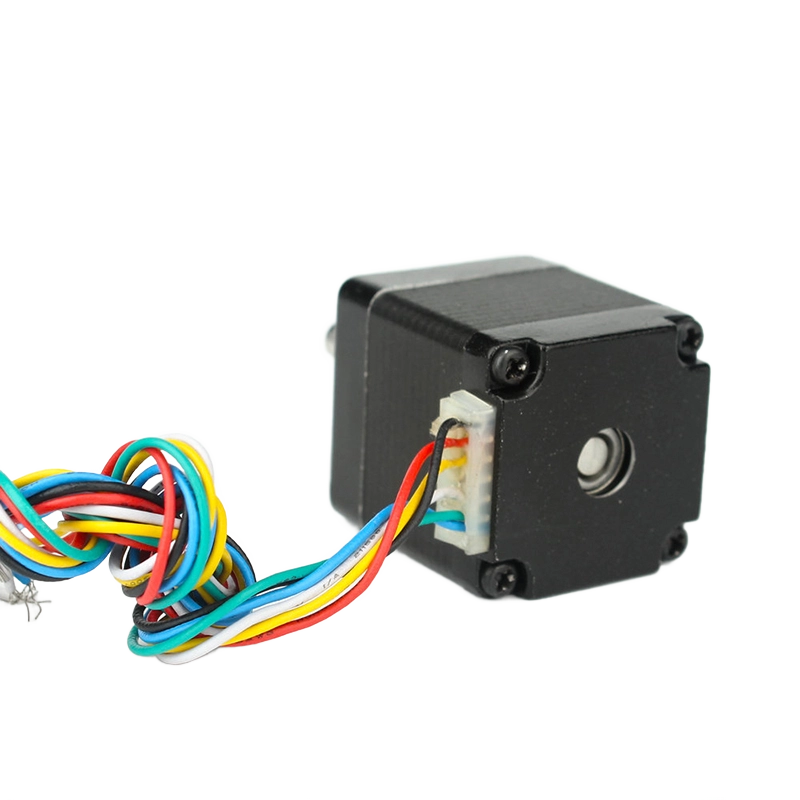
Selecting the correct base step angle profoundly influences your system performance. Engineers must balance speed, torque, and positioning granularity. The physical machining of the internal rotor directly establishes this baseline resolution. We typically evaluate two dominant industry standards for precision applications.
The 1.8° stepper motor serves as the widespread industry standard. It requires 200 distinct steps to complete one full 360-degree revolution. This configuration provides an optimal balance for most industrial and automation applications. You get robust torque output, respectable top speeds, and sufficient positioning accuracy for standard linear actuators and conveyors. The magnetic poles are spaced to allow rapid coil switching, supporting reliable mid-speed operation.
High-resolution alternatives exist for more demanding environments. The 0.9° stepper motor doubles the mechanical resolution, requiring 400 steps per revolution. Halving the step angle becomes necessary for tasks like optical alignment, precise fluid dispensing, and 3D printing. However, this finer resolution introduces a trade-off. Packing twice as many teeth into the same rotor diameter typically results in slightly lower holding torque. Additionally, the drive must send pulses twice as fast to achieve the same rotational speed, which limits the effective top-end RPM.
You must understand a critical non-cumulative error principle regarding these mechanical angles. A typical mechanical step error measures ±5%. Importantly, this error represents 5% of one individual step angle, not 5% of the total rotation. Furthermore, this error is strictly non-cumulative. If you command a 360-degree rotation, the motor will always end exactly where it should. Taking 200 steps or 2,000 steps does not stack the physical error. The magnetic fields continually realign the rotor to the absolute machined position of the stator.
Resolution and Performance Chart | ||
Specification Metric | 1.8° Standard Motor | 0.9° High-Resolution Motor |
|---|---|---|
Steps Per Revolution | 200 | 400 |
Positional Granularity | Excellent for general automation | Superior for optics and dispensing |
Typical Torque Profile | Higher baseline holding torque | Slightly reduced holding torque |
Speed Capability | Better performance at mid-to-high speeds | Limited top speed due to high pulse rates |
Engineers frequently turn to modern drive electronics to enhance system performance. Microstepping technology represents the most common electronic upgrade. Drives divide a single full mechanical step into smaller electrical increments. Common divisions include 16, 32, or even 256 microsteps per full step. You drastically improve low-speed smoothness and eliminate harsh resonance vibrations using this technique.
However, we must clarify a common engineering misconception regarding resolution versus accuracy. Microstepping vastly improves resolution, allowing the controller to command highly granular movements. It does not overcome the physical ±5% mechanical accuracy limit of the motor itself. The true positional accuracy remains bound by the internal magnetic and physical machining tolerances. Commanding a 1/256th microstep does not guarantee the shaft moves exactly that minute physical distance, especially under load.
Designers face unique challenges in highly constrained spaces. Medical devices, automated pipettes, and motorized camera lenses require extreme miniaturization. The micro stepper motor delivers precise movement in these tiny form factors. Scaling down the physical dimensions requires meticulous manufacturing. The magnetic gaps between the microscopic rotor teeth and stator become incredibly narrow. Despite their small footprint, they maintain the same proportional ±5% non-cumulative error rate as their larger counterparts, ensuring precise dosing or lens focusing.
You must also account for torque degradation during microstepping implementation. Incremental holding torque decreases significantly as you increase the microstep divisions. Consider these practical constraints:
A full step utilizes 100% of the motor's rated holding torque.
A half-step division drops the incremental holding torque to approximately 70%.
A 1/16th microstep provides less than 10% incremental holding torque to reach the next discrete position.
If the external friction exceeds this tiny incremental torque, the motor will not move until enough microsteps accumulate to overcome the load.
Choosing between architectures determines the overall success of your motion platform. You must frame the decision logic around your actual application requirements. Steppers win decisively in high-torque, low-speed, and highly repetitive applications. When cost-efficiency and system simplicity remain paramount, the open-loop architecture excels. You can connect a drive, send a pulse train, and achieve exact positioning reliably. They are ideal for CNC routers, 3D printers, and automated inspection stages.
Conversely, you must objectively recognize when servos are strictly required. High-speed dynamic loads demand continuous feedback. If your system encounters unpredictable, rapidly varying external forces, an open-loop system will fail. Applications requiring absolute, failure-proof closed-loop feedback must utilize servos. They excel at recovering from sudden mechanical disturbances and operating efficiently at extremely high RPMs.
However, you gain a massive advantage in the cost-to-precision ratio when utilizing open-loop architectures. You completely eliminate the need for delicate optical encoders. You avoid complex, time-consuming PID tuning software. You also bypass the need for expensive, highly sophisticated servo drives. By stripping away these extra layers of complexity, you dramatically lower the barrier to entry for precise positioning. The overall architecture remains leaner, more robust in harsh environments, and significantly easier to troubleshoot during field maintenance.
Every technology carries inherent physical limitations. Recognizing these risks early in the design phase prevents costly prototype failures. We must address resonance, load capacities, and thermal outputs to guarantee reliable positional accuracy over a long lifespan.
Mid-frequency resonance is a harsh physical reality for these motors. Because they move in discrete increments, each step acts like a tiny hammer blow to the rotor. At specific speed bands—typically between 100 and 200 RPM—these vibrations can amplify. If the resonance matches the natural frequency of your mechanical frame, the motor will stall and lose its position. You can mitigate this by utilizing mechanical elastomer dampers, implementing high-division microstepping, or programming your controller to accelerate rapidly past the known resonance speed bands.
The primary vulnerability of any open-loop system remains the risk of missed steps. The controller blindly assumes the shaft executed every commanded pulse. If an external load spike exceeds the available motor torque, the magnetic lock breaks. The shaft stalls, but the controller keeps counting. This results in complete positional corruption. You must advise your team to implement proper torque margin safety factors. Industry best practices dictate maintaining a 30% to 50% safety margin above your highest calculated dynamic load.
Thermal management also demands careful attention. These devices draw near-maximum current even when holding perfectly still. This constant electrical draw generates substantial heat. If not managed, excess heat degrades the internal magnet strength and damages coil insulation. You should outline clear duty cycle expectations. If the application allows, program the drive to reduce holding current by 50% when the motor is idle, significantly reducing the thermal load.
Design Risks and Mitigation Strategies | ||
Implementation Risk | Physical Cause | Effective Mitigation Strategy |
|---|---|---|
Mid-Frequency Resonance | Discrete stepping increments causing harmonic vibration buildup. | Install mechanical dampers; utilize microstepping; avoid running at critical speeds. |
Missed Steps (Stalling) | External load friction or inertia exceeding available magnetic torque. | Apply a 30-50% torque safety margin; reduce acceleration profiles. |
Excessive Heat Generation | Continuous high current draw during standstill holding phases. | Implement idle current reduction in the drive; attach appropriate heat sinks. |
Transitioning from concept to hardware requires strict specification logic. You must first define your exact success criteria. Establish the required positioning tolerance before evaluating any motor catalogs. Determine if your mechanism needs to hit a target within 0.1 degrees or 0.01 millimeters. Knowing this absolute physical tolerance dictates whether a standard step angle suffices or if a high-resolution model is mandatory.
Next, you must calculate your load inertia. Torque alone does not guarantee precise motion. The inertia matching ratio between the motor's internal rotor and the external attached load is critical. If a massive load connects to a tiny rotor, the motor will struggle to start and stop precisely, leading to stalling. Aim for an inertia mismatch ratio no greater than 10:1 for reliable, stall-free positioning during rapid acceleration phases.
We recommend moving quickly from theoretical sizing to practical hardware validation. Request detailed pull-out torque curves from the manufacturer. These charts reveal exactly how much torque drops off as speed increases. Evaluate different NEMA frame sizes to see what physically fits your chassis. If your load risks are exceptionally high but you still want simple controls, consult an application engineer about closed-loop hybrid options. These hybrid systems add a simple encoder to correct missed steps autonomously while keeping the basic drive architecture intact.
The core value of this motor architecture lies in its absolute physical predictability. High holding torque securely locks payloads in place, eliminating the constant jitter associated with closed-loop continuous motors. By converting digital pulses directly into discrete mechanical increments, you achieve highly reliable positional accuracy.
They are not blanket replacements for servos in highly dynamic, high-speed environments. However, they undoubtedly remain the most robust and reliable choice for precision open-loop positioning. By eliminating complex encoders and tuning software, you streamline your entire machine design. You gain immediate, predictable control over your load.
Take the next step in your design process today. Review the technical datasheets for your targeted NEMA frame sizes. Download the appropriate CAD files to verify mechanical fitment. Contact our technical sales team for expert sizing assistance and ensure your next motion control project operates flawlessly.
A: Yes. Because they move in discrete, machined increments, they provide exact open-loop positioning. This remains true provided the external load does not exceed the motor's torque capabilities, which would result in missed steps.
A: A 0.9° model offers double the mechanical resolution per revolution compared to a 1.8° model. It provides finer baseline physical increments, granting superior accuracy before you rely on any electronic microstepping adjustments.
A: It increases your commanded resolution and vastly improves low-speed smoothness. However, the true mechanical accuracy is still firmly bound by the physical machining tolerances of the internal rotor teeth.


