close
Choose Your Site
Global
Social Media
Views: 0 Author: Site Editor Publish Time: 2026-09-17 Origin: Site
Selecting the right motor architecture represents a critical engineering crossroad where the choice between mechanical simplicity and electronic precision dictates the entire product lifecycle. Specifying the wrong motor architecture leads to compounding issues on the production floor and in the field. You might face over-engineered assemblies and complex controllers on one side. On the other side, you risk premature mechanical failure, excessive maintenance downtime, and severe thermal inefficiencies. A structured evaluation of brushed and brushless motor technologies is essential for any hardware project. Focusing on performance metrics, long-term operational expenses, and application-specific constraints guides the final procurement or design decision. Engineers must weigh the immediate ease of integration against the long-term reliability required by the end user. This technical evaluation breaks down the mechanical, electrical, and environmental differences between the two primary DC motor types to help you specify the exact right component for your next assembly.
Commutation dictates lifespan: Brushed motors rely on physical contact (brushes and commutators) which inherently limits lifespan due to friction and wear, whereas brushless designs offer virtually maintenance-free operation limited only by bearing life.
Control complexity vs. mechanical simplicity: Brushed motors can operate with simple direct current, while brushless motors require complex electronic speed controllers (ESCs) to manage phase switching.
Power density and efficiency: Brushless motors deliver higher torque-to-weight ratios and better thermal dissipation, making them critical for compact, high-performance applications.
Cost evaluation requires a comprehensive lens: While the upfront cost of a brushed motor is lower, the long-term maintenance, replacement rates, and energy consumption often make brushless technology more cost-effective at scale.
Brushed DC motors rely on a straightforward, time-tested internal structure. The stator consists of permanent magnets that remain stationary inside the motor housing. The rotor, often called the armature, contains copper coils and spins within this stationary magnetic field. A mechanical commutator sits on the rotor shaft, divided into copper segments. Carbon brushes, held in place by spring tension, press directly against this spinning commutator. As the rotor turns, the brushes physically transfer electrical current from the power source to the commutator segments. This physical action reverses the magnetic field in the coils, keeping the motor spinning continuously.
However, this physical commutation process creates inherent physical limitations that engineers must account for during the design phase. The continuous sliding contact between the carbon brushes and the copper commutator generates significant friction and heat. Mechanical wear degrades the brushes over time, meaning they are consumable components that will eventually fail. Furthermore, as the brushes wear down, carbon dust accumulates inside the motor housing. This conductive dust can cause electrical shorts if not cleaned out regularly, requiring periodic maintenance schedules that increase the overall operational burden on maintenance teams.
The brush material itself also dictates performance. Harder carbon brushes last longer but wear down the copper commutator faster. Softer graphite brushes protect the commutator but require more frequent replacement. Engineers must balance these factors based on the expected duty cycle of the application. In high-vibration environments, brush bounce becomes a serious issue. If the spring tension cannot keep the brush in constant contact with the commutator, the motor experiences power interruptions and severe electrical arcing, which rapidly destroys the contact surfaces.
A Brushless Motor uses an inverted structural design compared to its brushed counterpart. The copper coils remain stationary on the stator, attached directly to the inside of the motor housing. The permanent magnets sit on the rotating rotor shaft in the center. This configuration completely eliminates the need for physical brushes and a mechanical commutator. Instead, the motor relies entirely on electronic commutation to keep the rotor spinning.
Electronic commutation requires a sophisticated control system. Hall effect sensors mounted on the stator track the exact position of the rotor's magnetic poles. In sensorless designs, the controller monitors the back-electromotive force (back-EMF) generated by the spinning magnets to determine rotor position. These sensors communicate with an external electronic speed controller (ESC). The ESC sequences the current through the stator windings at precise intervals, creating a rotating magnetic field that drags the rotor along with it. This electronic switching happens thousands of times per second, requiring fast microprocessors and robust power MOSFETs.
Eliminating physical contact points drastically improves mechanical integrity and electrical efficiency. No energy is lost to brush friction, and no electrical power is wasted through mechanical arcing. The only wearing parts inside a brushless motor are the steel ball bearings supporting the rotor shaft. This fundamental shift from mechanical switching to electronic switching allows brushless motors to achieve significantly higher speeds, better thermal performance, and a lifespan that outlasts the equipment they are installed in.
Efficiency curves differ significantly between the two architectures, directly impacting power consumption and heat generation. A brushless motor typically operates at 85 to 90 percent electrical efficiency. Brushed variants generally peak around 75 to 80 percent efficiency, with that number dropping as the brushes wear down and contact resistance increases. Thermal dissipation dynamics explain a large part of this performance gap and dictate how engineers must design the surrounding equipment enclosure.
Brushless motors feature windings on the stationary stator. These windings attach directly to the outer metal casing of the motor. This design allows for superior heat sinking. Heat generated by the copper coils transfers easily through the stator iron to the external environment or a mounted heat sink. In contrast, brushed motors trap heat on the inner spinning rotor. Cooling a spinning mass is inherently more difficult. The heat must radiate across the air gap to the outer casing, which is highly inefficient. Brushed motors often require external ventilation holes to allow airflow, which exposes internal components to environmental hazards.
Thermal Characteristic | Brushed DC Motor | Brushless DC Motor |
|---|---|---|
Primary Heat Source Location | Spinning Rotor (Armature) | Stationary Stator |
Heat Dissipation Path | Poor (Radiates across air gap) | Excellent (Direct conduction to casing) |
Ventilation Requirement | Often requires open vents | Can be fully enclosed/sealed |
Continuous Load Capability | Limited by internal heat buildup | High, easily managed with external heat sinks |
Speed and torque characteristics dictate application suitability. Brushless motors maintain flat torque curves across a much wider speed range. They operate without the risk of brush bounce at high RPMs, allowing them to spin at speeds exceeding 50,000 RPM in certain applications. Brushed motors are typically limited to lower speeds because high centrifugal forces can cause the commutator segments to fly apart or the brushes to lose contact.
Rotor inertia plays a major role in dynamic response. Brushless motors place permanent magnets on the rotor. This creates a much lower inertia profile compared to the heavy copper-wound rotors of brushed motors. Lower inertia enables faster acceleration and deceleration profiles. When a machine needs to start, stop, or reverse direction instantly, the low-inertia brushless rotor responds immediately to the controller's commands.
Power density is a critical metric for modern engineering. A compact 70mm BLDC motor can achieve the same or greater continuous torque output as a significantly larger brushed motor. This saves critical space and reduces overall weight in tight assemblies like robotic arms, drone chassis, and portable medical devices. Engineers can downsize the motor frame without sacrificing mechanical output.
Acoustic emissions impact user experience, workplace safety, and equipment precision. The mechanical sliding contact in brushed motors generates continuous high-frequency friction noise. The physical interaction between the brushes and the commutator also causes noticeable vibration that transfers through the motor shaft into the driven load. In precision optics or sensitive measuring equipment, this vibration is unacceptable.
Brushless designs offer near-silent operation. The lack of mechanical friction eliminates the primary source of motor noise. The only sounds generated are the hum of the bearings and the high-frequency switching noise from the electronic controller, which can usually be tuned out of the audible range. This makes brushless architecture the preferred choice for noise-sensitive environments. Medical equipment, laboratory centrifuges, and high-end consumer products rely heavily on this quiet operational profile to meet strict noise regulations.
Expected lifespans vary dramatically based on the commutation method. Brushed designs typically last 1,000 to 3,000 hours under normal load conditions before the brushes wear down completely. Brushless designs routinely exceed 10,000 to 20,000 hours of operation. Ball bearing longevity dictates the lifespan of a brushless motor, rather than electrical wear. Once the bearings fail, the motor is usually replaced entirely.
Real-world maintenance overhead for brushed motors is substantial and requires dedicated labor. Maintenance teams must follow strict protocols to keep brushed motors operational in industrial settings.
Inspect brush length every 500 hours of operation.
Replace carbon brushes before they wear down to the shunt wire.
Blow out accumulated carbon dust from the motor housing using compressed air.
Inspect the copper commutator for pitting, grooving, or burn marks.
Machine the commutator on a lathe to restore a smooth contact surface if severe grooving occurs.
Re-seat new brushes using a seating stone to ensure proper contact arc.
Upfront Bill of Materials (BOM) costs heavily favor older brushed technologies. Brushed units offer a significantly lower entry cost for simple applications. The manufacturing process is highly automated and relies on cheap materials like copper wire and stamped steel. However, brushless stators require complex winding machinery. They utilize expensive rare-earth magnets like neodymium on the rotor. Furthermore, every brushless motor requires an electronic controller to function, which adds microprocessors, MOSFETs, and circuit boards to the initial price tag.
Evaluating long-term value requires looking past the initial purchase order. Engineers must factor in long-term downtime and replacement labor. When a brushed motor fails on an assembly line, the cost of lost production far exceeds the price of a new motor. Shipping delays for replacement parts halt production lines. Energy savings over a 5-to-10-year operational lifecycle often offset the higher initial component costs of brushless systems. A brushless motor drawing 10% less power running 24/7 will pay for its higher upfront cost through reduced electricity bills alone.
Integration overhead differs drastically based on the motor type. Brushed motors require simple two-wire connections. You apply a DC voltage, and the motor spins. Reversing the polarity reverses the direction. Basic Pulse Width Modulation (PWM) easily handles speed control by rapidly turning the power on and off. This simplicity makes brushed motors ideal for basic circuits without microcontrollers.
Brushless systems demand significantly more engineering resources. You must integrate a dedicated Electronic Speed Controller (ESC). Managing commutation sensor alignment is necessary, whether using Hall-effect sensors, optical encoders, or resolvers. Engineers must tune Proportional-Integral-Derivative (PID) loops to ensure smooth acceleration and maintain firmware updates for the controller. The wiring harness increases from two heavy-gauge wires to three phase wires plus five or more thin sensor wires.
However, this complexity brings massive advantages. Brushless designs inherently support precise positioning and velocity feedback. Closed-loop operation is native to the design because the controller already knows the exact rotor position for commutation. Brushed systems require auxiliary add-on encoders mounted to the rear shaft to achieve comparable closed-loop control, which adds length, cost, and complexity to the brushed assembly.
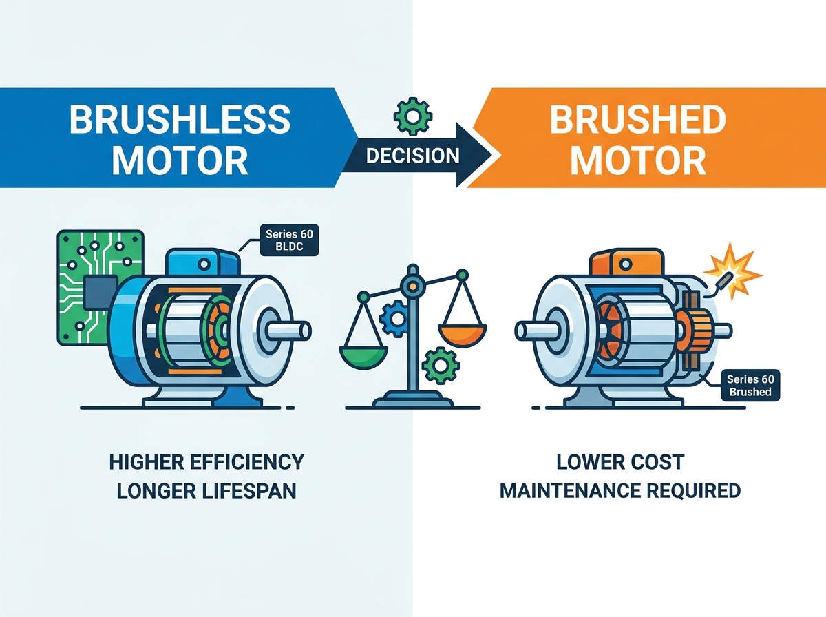
Standardizing motor frames across a single product line simplifies manufacturing, reduces inventory overhead, and streamlines mechanical design. Engineering teams often face challenges when upgrading legacy systems to modern standards without changing the physical mounting plates. Comparing the Series 60 Brushless DC Motor against the Series 60 Brushed DC Motor highlights these exact trade-offs in a drop-in replacement scenario.
In this specific 60mm form factor, the brushless variant offers substantially higher continuous torque and lower rotor inertia. It also provides superior IP-rated sealing capabilities because it does not require ventilation for brush dust. This makes the brushless version ideal for upgrading a machine's performance without redesigning the chassis. Conversely, the brushed variant offers a lower barrier to entry for legacy system integration. It utilizes simpler wiring harnesses, making it easier to deploy when advanced control electronics are unavailable or when the existing control panel only outputs a simple two-wire DC voltage.
Electromagnetic interference (EMI) poses significant risks in complex assemblies containing sensitive microprocessors or analog sensors. Brushed motors generate severe electrical noise and physical arcing at the commutator interface. Every time a brush breaks contact with a commutator segment, a small electrical arc occurs. This arcing broadcasts broadband radio frequency interference (RFI). This interference can disrupt sensitive nearby electronics, corrupt analog sensor lines, and cause complete failures during strict EMC compliance testing, such as FCC or CE certification.
Brushless motors mitigate this specific risk through electronic switching. They do not produce mechanical arcing because there are no breaking physical contacts. However, engineers must still manage high-frequency switching noise. The PWM frequencies generated by the electronic controller create their own EMI challenges. Proper shielding of the phase wires, utilizing twisted pairs for sensor lines, and implementing robust grounding techniques are mandatory to pass EMC testing with a brushless system.
Environmental risks dictate motor selection in harsh field conditions. Brushed motors are typically open to the environment. Vents allow for heat dissipation and provide an exhaust path for the carbon dust generated by the brushes. This open design makes them highly susceptible to external dust, moisture ingress, and internal corrosion. If water enters a brushed motor, it immediately shorts the commutator.
Furthermore, commutator sparking creates a severe explosion risk. Brushed motors are highly hazardous in explosive environments containing volatile gases, chemical vapors, or combustible powders. They rarely pass ATEX or HazLoc certifications without massive, heavy explosion-proof enclosures. Brushless motors solve these environmental vulnerabilities entirely. Because they dissipate heat externally through the stator and lack exposed mechanical contact points, they can be fully sealed. Engineers routinely specify brushless motors with IP65 or IP67 ratings, allowing them to operate underwater or in heavy dust environments safely.
Brushed motors remain highly viable for specific, well-defined use cases. Cost-sensitive consumer goods benefit heavily from their low component price. Low-duty cycle applications with short overall operational lifespans fit this profile perfectly. Automotive seat adjusters, power mirrors, and windshield wipers rarely exceed a few hundred hours of total runtime over the life of the vehicle. Extreme budget constraints often force the use of brushed technology. Legacy systems lacking complex control electronics also require the simplicity of a two-wire brushed motor to function without a complete electrical redesign.
Brushless motors dominate demanding, continuous-duty applications. High-reliability industrial automation relies on their extended lifespan to prevent line shutdowns. Surgical and medical instruments require their quiet, vibration-free operation to ensure surgeon precision. Aerospace actuators depend on their high power density and low weight to maximize payload capacity. Battery-powered tools require maximum run-time efficiency, which only brushless designs provide. Environments requiring sealed, spark-free operation mandate the use of brushless technology to ensure facility safety and regulatory compliance.
Define your continuous torque and peak torque requirements before selecting a motor frame size to avoid overheating.
Evaluate your available physical space for both the motor housing and the mandatory electronic speed controller.
Calculate the expected operational hours per year to determine if bearing life or brush wear will cause the first mechanical failure.
Review your environmental conditions to see if IP-rated sealing or spark-free operation is mandatory for safety compliance.
Consult with an application engineer to finalize wiring harnesses and request detailed technical specification sheets.
A: The primary difference lies in the commutation method. Brushed motors use physical carbon brushes and a mechanical commutator to switch current direction. Brushless motors use electronic speed controllers and sensors to sequence current without any physical contact, eliminating friction and wear.
A: Direct physical replacement is sometimes possible if the frame sizes match. However, you cannot simply swap the wiring. A brushless motor requires a new electronic speed controller, specific sensor wiring, and potentially different mounting or shaft adaptations.
A: Brushless motors cost more due to their internal components. They utilize expensive rare-earth magnets on the rotor. The stator winding process is more complex. Additionally, they require a mandatory electronic controller to operate, which adds to the initial component cost.
A: While the electrical components are largely maintenance-free, the motor still contains moving parts. The internal ball bearings support the rotor shaft. These bearings will eventually wear out over time and require replacement, though this takes significantly longer than brush wear.
A: Brushless motors are vastly superior for battery-powered applications. They operate at higher electrical efficiencies because they do not lose energy to brush friction or arcing. This higher efficiency translates directly to longer battery run-times per charge.
A: No, brushed motors are generally unsafe for hazardous environments. The physical contact between the brushes and commutator creates continuous electrical sparking. This sparking can ignite flammable gases, vapors, or combustible dust present in the atmosphere.
A: A similar brushed motor typically lasts 1,000 to 3,000 hours before the brushes wear out. A 70mm BLDC motor easily exceeds 10,000 hours of operation. Its lifespan is limited only by the mechanical durability of its internal ball bearings.