
close
Choose Your Site
Global
Social Media

Views: 0 Author: Site Editor Publish Time: 2026-07-06 Origin: Site


In automation and precision engineering, selecting between a DC stepper motor and a brushless DC (BLDC) motor dictates system architecture, software complexity, and long-term reliability. Engineers frequently face a crossroads when balancing component capabilities against operational demands. While both motor types offer high reliability compared to brushed alternatives, their performance curves are fundamentally inverted. Misjudging these profiles leads to compromised designs, thermal bottlenecks, or unnecessary engineering overhead. Understanding their distinct mechanical behaviors is crucial for optimizing your next build. This guide skips the basic definitions and dives straight into the engineering trade-offs and empirical performance metrics. You will learn how to evaluate torque delivery, positioning control, and frame size constraints. We also provide actionable insights required to make a secure sourcing decision for your precise application.
Torque vs. Speed: A DC stepper motor excels at low-speed torque and holding position, while a BLDC motor maintains consistent torque at high speeds.
Control Architecture: Steppers operate on cost-effective, simple open-loop systems; BLDC motors require closed-loop feedback and sophisticated driver programming.
Total Cost of Ownership (TCO): Steppers offer a lower upfront barrier. BLDCs present higher initial costs (motor + encoder + driver) but yield higher efficiency and thermal management at scale.
Sizing Parity: Frame size dictates output. Upgrading from NEMA-standard steppers to high-density options like a 60mm BLDC motor or an 86mm BLDC motor requires mechanical and controller redesigns.
Every engineering project demands a clear performance baseline. You must frame your initial decision around non-negotiable system requirements. Consider whether you are prioritizing absolute positioning without complex encoders or dynamic speed response under varying loads. An open-loop setup provides predictable positioning if you maintain speeds within safe margins. Conversely, systems requiring rapid acceleration and high continuous torque naturally push you toward closed-loop architectures.
Engineers often worry about the "missed steps" risk inherent to open-loop designs. If a sudden mechanical load exceeds the holding torque of a stepper, the rotor desynchronizes from the stator field. The controller remains unaware of this positional loss. You can prevent this by oversizing the motor, but this increases bulk and power consumption. In contrast, BLDC systems eliminate missed steps through continuous feedback. However, they introduce significant tuning complexities. You must configure PID loops meticulously to prevent oscillation around the target position.
Energy consumption and thermal budgets also dictate motor selection heavily. Steppers draw continuous current. They energize their coils fully even at a complete standstill to maintain holding torque. This generates substantial heat, complicating thermal management in enclosed spaces. BLDC units operate differently. They only consume current proportional to the mechanical load. If the load is light, current draw remains minimal. This proportional energy use makes them ideal for battery-operated devices or thermally sensitive environments where heat dissipation is difficult.
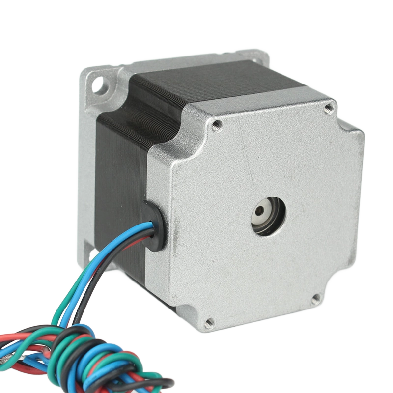
Torque delivery separates these two technologies most distinctly. A DC Stepper Motor provides its maximum torque at zero RPM. This exceptional holding torque locks mechanisms firmly in place without requiring mechanical brakes. However, this advantage fades quickly. As RPM increases, coil inductance and back-EMF limit how fast current can enter the windings. This causes a steep, predictable torque drop-off. Running a stepper at high velocities severely compromises its ability to move loads reliably.
BLDC continuous torque profiles look entirely different. They offer flat, consistent torque curves from zero up to their rated speeds. Because they rely on electronic commutation synchronized to rotor position, back-EMF does not throttle their performance prematurely. This flat torque curve makes them mandatory for high-velocity applications. Spindle drives, fast traction wheels, and rapid indexing conveyors all rely on this continuous output.
Resolution in stepper systems relies on mechanical construction. A standard hybrid stepper operates at 1.8 degrees per step, yielding 200 distinct steps per revolution. Engineers often employ microstepping to increase smoothness. You can divide each physical step into smaller electrical increments. While microstepping drastically reduces resonance and vibration, it does not linearly increase accuracy under heavy loads. Incremental torque drops significantly between microsteps, causing positional errors if resistance is high.
BLDC motors take a fundamentally different approach to positioning. They inherently rely on feedback loops to function. Because the controller must know the exact rotor position to sequence the phases correctly, you must integrate Hall effect sensors or external encoders. This guarantees positioning accuracy and prevents stalling. However, this requirement adds wiring complexity. It introduces new potential points of failure and demands more sophisticated control algorithms to manage the constant data stream.
Physical space constraints often force engineers to re-evaluate their motor choices. BLDC designs offer a significantly higher power-to-weight ratio. Their rotors lack heavy windings, reducing internal inertia and allowing faster acceleration. A machine currently utilizing a bulky NEMA 34 DC stepper motor might achieve identical or superior dynamic performance by downsizing. Transitioning to a compact, thermally efficient alternative frees up mechanical envelope space and reduces overall system weight.
When space is at a premium but speed remains critical, integration requires careful sizing. The 60mm BLDC motor serves as an industry standard here. Engineers frequently deploy this form factor in medium-payload robotics, automated packaging machinery, and AGV drive wheels. It balances high torque density and compact dimensions perfectly. You gain dynamic responsiveness without demanding massive driver cabinets or heavy structural supports.
Industrial scaling demands even higher continuous output. Heavy-duty applications require robust solutions capable of handling massive radial and axial loads. When you need to specify an 86mm BLDC motor, you are typically outfitting CNC axes or heavy industrial automation equipment. This size serves as the premier choice when replacing large steppers. You should select this size when high continuous RPM, aggressive duty cycles, and closed-loop reliability are absolute necessities.
Evaluating financial impact requires looking beyond the motor itself. As a standalone unit, a standard stepper is undeniably cheaper. Stamped laminations and simpler rotor designs keep manufacturing costs low. However, you must evaluate the complete system cost. Stepper drivers are inexpensive, but many modern designs require closed-loop verification. Adding secondary encoders to verify steps bridges the cost gap significantly. Once you add encoders, specialized drivers, and extra wiring, the financial advantage over a BLDC system narrows rapidly.
Development time represents a massive hidden trade-off. Steppers function as reliable "plug-and-play" components. You simply send step and direction signals from a basic microcontroller. They execute the movement immediately. BLDC integration demands extensive engineering hours. You must program complex motor controllers, tune PID loops, and manage Hall sensor data. Software development for precise BLDC positioning requires experienced personnel and thorough testing phases.
Acoustic noise and ongoing maintenance also differentiate these systems. Steppers inherently cause resonance and vibration. Their discrete stepping motion excites mechanical structures, especially at specific mid-band frequencies. This noise can be unacceptable in certain environments. Conversely, BLDC operation remains exceptionally smooth and quiet. This silent operation proves critical for medical devices, consumer-facing technology, and laboratory automation where mechanical vibration compromises results.
Choosing the correct motor requires aligning mechanical realities against software capabilities. You must objectively evaluate your operational parameters before requesting datasheets.
Evaluation Metric | DC Stepper Motor | BLDC Motor |
|---|---|---|
Optimal Speed Range | Low to Medium (< 1000 RPM) | Medium to High (up to 10,000+ RPM) |
Holding Torque | Excellent at 0 RPM | Requires continuous current/active loop |
Control Method | Open-loop (Step/Dir) | Closed-loop (PWM/Commutation) |
Thermal Profile | High heat generation at rest | Proportional to load; runs cooler |
You should unequivocally specify a stepper motor for applications demanding low-speed precision on a strict budget. They dominate in 3D printers, low-speed camera gimbals, and simple linear actuators. Use them whenever loads remain highly predictable, operating speeds stay below 1000 RPM, and absolute positioning without feedback is acceptable.
You should unequivocally specify a BLDC motor for dynamic, high-efficiency environments. They are the standard for Autonomous Mobile Robots (AMRs), drone propulsion, and high-speed CNC spindles. Scenarios demanding high power density necessitate their use. For example, utilizing a 60mm or 86mm BLDC motor for payload handling ensures maximum throughput without thermal stalling.
Follow these next steps for effective procurement:
Audit the Mechanical Envelope: Measure available mounting space to determine if you need compact high-density framing.
Assess Power Supply Limits: Calculate peak current draw versus continuous draw to size your power units correctly.
Evaluate Software Capabilities: Confirm your engineering team has the bandwidth and expertise to manage closed-loop tuning.
Determine Thermal Constraints: Verify whether the installation environment can handle constant heat dissipation.
Neither motor configuration is objectively better in a vacuum. The ideal choice depends entirely on your specific mechanical and electronic constraints. The stepper motor remains the undisputed champion of low-speed, high-holding-torque precision. It provides unmatched simplicity for predictable loads. Conversely, the BLDC motor stands as the essential choice for high-speed, high-efficiency, and dynamic load-bearing systems.
Base your final procurement not on standalone component price, but on system-level requirements. Evaluate your target RPM, enforce strict thermal limits, and honestly assess available engineering resources for controller integration. By mapping your load profile accurately, you guarantee a robust, long-lasting motion control system.
A: A closed-loop stepper bridges the performance gap significantly. It prevents missed steps and runs cooler by dynamically adjusting current based on encoder feedback. However, it still suffers from fundamental torque drop-off at high speeds. It cannot match the flat, continuous high-RPM torque delivery of a true BLDC.
A: Steppers continuously draw maximum rated current to maintain holding torque, even when stationary. This constant electrical energy converts into substantial heat. BLDCs draw current proportionally. They only consume the energy required to move the immediate mechanical load, resulting in much lower thermal output during intermittent operations.
A: Rarely. Faceplate dimensions may roughly align—an 86mm BLDC motor is similar in width to a NEMA 34. However, shaft lengths, pilot diameters, and mounting hole patterns differ. Crucially, their driver connections and feedback wiring require entirely distinct hardware and software configurations.
A: Mechanically, bearings limit both motors since neither uses physical brushes. Bearing wear dictates the physical failure point. However, the lower thermal output of a BLDC generally preserves bearing lubrication longer. This results in an extended operational lifespan during continuous-duty applications.


