
close
Choose Your Site
Global
Social Media
Views: 0 Author: Site Editor Publish Time: 2026-05-28 Origin: Site


Choosing a motor is rarely about picking the cheapest option off a shelf. When engineers guess at torque requirements, machinery often fails in the field. Specifying the wrong stepper motor leads to lost steps, system resonance, or overheating components. These failures directly impact production downtime and product reliability. Selecting the optimal motor requires careful mechanical balancing. You must evaluate the dynamic torque-speed curve carefully. You also need to identify accurate load profiles for your specific application. Furthermore, you must ensure strict compatibility between the motor's phase current and the driver's thermal limits. We wrote this guide to provide a highly technical, step-by-step evaluation framework. You will learn how to size and select stepper motors based on mechanical constraints, application environments, and driver capabilities. Let us break down the exact physics you need for a reliable build.
Always build in a 30% safety margin above your calculated peak torque requirements to account for friction and mechanical wear over time.
Microstepping improves smoothness but compromises precision under heavy loads; do not rely on it as a substitute for an inherently higher-resolution motor or gearing.
Never size a motor without sizing the driver. A high-inductance motor paired with a low-voltage driver will suffer severe torque degradation at higher speeds.
Map torque directly to frame size: NEMA 17 is typically suited for sub-0.8 N.m loads, NEMA 23 for 1–3 N.m, and NEMA 34 for extreme applications exceeding 3 N.m.
You cannot select a motor without defining the physical load first. Total load torque combines friction torque and inertia torque. You use Newton's second law to calculate the force needed to accelerate your specific mass. You then multiply this force by the pulley or wheel radius to find the rotational torque. Relying purely on estimates here guarantees poor performance. We recommend mapping out a clear operational sequence.
Calculate the static friction of the idle system.
Determine the peak acceleration rate required.
Compute the dynamic inertia torque during acceleration.
Add these values together to find your absolute minimum torque threshold.
Mobile robotics introduce complex environmental variables. You must factor in extra torque requirements for scaling inclines. Pushing a load up a ramp requires compensating for gravity. You also need to verify the slip torque limit. Ensure your motor's output does not exceed the maximum friction torque your wheels can transfer to the ground. If motor torque exceeds traction limits, the wheels will spin out. This causes complete traction failure and positioning errors.
Engineers often make the mistake of evaluating motors based on holding torque alone. Holding torque only applies when a motor is stationary. You must assess the dynamic pull-out torque available at your target operating RPM. Torque naturally decays at higher speeds due to coil inductance. Always reference the manufacturer's torque-speed curve chart. Find your target speed on the X-axis and verify the available torque on the Y-axis.
Theoretical math rarely matches real-world conditions perfectly. Mechanical wear increases friction over time. Bearings degrade, and lubrication dries up. Multiply your theoretical maximum torque requirement by 1.3 to establish a 30% buffer. This safety margin establishes a robust baseline specification. It prevents stalling during unexpected mechanical bind-ups.
The NEMA standard dictates the physical faceplate dimensions of a motor. It does not dictate motor length, but faceplate size directly correlates to torque capacity. Larger frames hold larger magnetic rotors and more copper windings. We can map your calculated torque needs directly to standard sizes.
Torque Requirement | Recommended NEMA Size | Primary Applications |
|---|---|---|
Sub-0.8 N.m | NEMA 17 | Medical devices, 3D printers, small linear actuators |
1.0 to 3.0 N.m | NEMA 23 | General automation, light CNC machining, conveyor systems |
Greater than 3.0 N.m | NEMA 34 | Heavy inertial loads, large mills, rigid positioning tables |
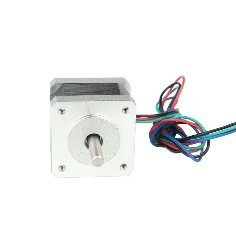
If your application demands less than 0.8 N.m of dynamic torque, evaluate a 42mm NEMA17 DC stepper motor. These compact units are ideal for short-distance, quick indexing operations. You will frequently find them in tight spaces inside medical devices. They also drive the X and Y axes on most desktop 3D printers. Their low rotor inertia allows for rapid acceleration profiles.
When load mass increases, you must step up to a 57mm NEMA23 stepper motor. This size functions as the standard workhorse for general automation. NEMA 23 units provide a balanced ratio of speed to holding force. They excel in light CNC machining operations and factory conveyor systems. They offer enough durability for continuous factory floor operations.
Extreme mechanical loads require you to specify an 86mm NEMA34 stepper motor. These massive motors drive large inertial loads where rigid positioning is critical. Heavy gantry systems rely entirely on this form factor. Engineers often pair NEMA 34 motors with planetary gearboxes. This combination prevents overshooting when decelerating massive steel components.
Standard motors often vibrate excessively during operation. Consider 5-phase stepper motors over standard 2-phase models for sensitive systems. 5-phase motors offer a smaller base step angle of 0.72 degrees. This internal geometry significantly reduces structural vibration. Low vibration is crucial for optical equipment, laboratory instrumentation, and camera sliders. They run inherently smoother across all speed bands.
Directly driving a heavy load causes control instability. Evaluate geared stepper motors for these situations. Adding a mechanical gearbox reduces the inertia ratio between the load and the motor. The motor feels a fraction of the actual load mass. This prevents missed steps during aggressive deceleration. Gearboxes also multiply torque output at the expense of top speed.
Open-loop systems cannot detect physical stalls. Upgrade to a closed-loop stepper motor for critical positioning tasks. These units feature an integrated rear encoder. The encoder provides constant pulse feedback to the controller. The controller can verify actual position against commanded position. This architecture bridges the reliability gap between simple steppers and expensive AC servo systems. It guarantees stall prevention.
Gravity constantly pulls down on Z-axis mechanics. Specify motors equipped with an integrated power-off electromagnetic brake. Standard steppers lose all holding torque when power cuts out. A power-off brake engages a mechanical friction pad the moment voltage drops. This prevents suspended loads from dropping and smashing expensive tooling during emergency stops or sudden power failures.
Every motor possesses a native mechanical resolution. Choose between 1.8-degree units and 0.9-degree units based on baseline stop accuracy requirements. A 1.8-degree motor provides 200 physical steps per revolution. A 0.9-degree motor provides 400 steps per revolution. Higher physical step counts yield better native precision. However, higher step count rotors often produce slightly less holding torque due to their tighter internal tooth spacing.
Drivers use microstepping to subdivide physical steps. Pushing 256 microsteps per full step effectively eliminates low-speed jerkiness. It cures audible resonance issues immediately. However, you must note a harsh engineering reality. Single-step positional accuracy degrades severely under heavy loads when heavily microstepped. The magnetic holding force between microsteps is extremely weak. Do not rely on microstepping for precision positioning against heavy mechanical resistance.
Stepper motors ring like bells under certain conditions. Identify the motor's natural resonance frequency. This typically occurs in the low-speed band below 100 Hz. If you dwell at this speed, the motor will vibrate violently and lose torque completely. Plan your system acceleration curve to push through this frequency band rapidly. Spending minimal time in the resonance zone is a fundamental best practice.
Marketing departments love peak current ratings. You must evaluate motor and driver compatibility based on Root Mean Square continuous current instead. RMS represents the actual thermal load the system can sustain. The formula is simple: RMS equals Peak multiplied by 0.707. If you size a driver based on peak current, it will overheat during continuous operation and trigger thermal shutdowns.
You face two primary choices when selecting drive architecture. Your choice dictates high-speed performance entirely.
L/R Drives (Constant Voltage): These simple drives supply a voltage matching the motor voltage. The ratio is strictly 1:1. They are acceptable only for low-speed devices, low-cost toys, or battery-operated tools. Inductance blocks current flow at high speeds, causing severe torque drop-off.
Chopper Drives (Constant Current): These industrial drives use high-frequency PWM switching. The supply voltage is significantly higher than the motor's rated voltage. A typical ratio is 8:1 or higher. This high voltage punches through coil inductance quickly. Chopper drives are absolutely mandatory for maintaining useful torque at high operating speeds.
Modern drivers offer advanced control logic. Ensure your drive supports necessary advanced features. Look for programmable acceleration ramping. Smooth ramps prevent the motor from stalling on startup when pulling heavy loads. You should also verify short-term current boost capabilities. A brief burst of excess current provides the extra force needed to overcome initial breakaway static friction.
Successful motor selection relies on a strict dependency chain. The mechanical load dictates the torque required. The torque dictates the proper NEMA frame size. The motor's phase current then dictates your driver selection. You cannot skip or reverse these steps. Furthermore, theoretical calculations cannot account for all system friction and environmental vibration. We strongly recommend physical prototyping. A physical test run is mandatory for finalizing your bill of materials. Use an external encoder to record the delta between commanded steps and actual steps. Only then can you trust your design in the real world.
A: Coil inductance is the culprit. Inductance increases electrical impedance as step pulse frequency rises. This limits the time current has to reach its maximum value inside the coil per step. Less current means a weaker magnetic field, resulting in a severe drop in dynamic torque at higher speeds.
A: Yes, you can use a larger driver safely. However, the driver must allow you to manually limit the output current to match the motor's rated phase current. Failing to limit this continuous current will rapidly overheat and melt the motor windings.
A: Holding torque measures the force required to physically turn a stationary, fully powered motor. Pull-out torque represents the usable dynamic force the motor can exert while actively spinning at a specific RPM without stalling or losing synchronization.


