
close
Choose Your Site
Global
Social Media
Views: 0 Author: Site Editor Publish Time: 2026-05-25 Origin: Site


Specifying a precise motion control solution is a critical decision in any engineering project. Choosing the wrong DC motor often sabotages otherwise perfect mechanical designs. Under-sizing leads directly to premature thermal failure and compromised reliability in the field. Conversely, over-sizing inflates your bill of materials costs while wasting valuable physical space inside your enclosure. Both mistakes drain engineering resources and delay critical product launches.
This guide provides a quantitative, risk-aware framework to prevent those costly errors. We will walk you through evaluating exact torque requirements. You will learn how to map out harsh environmental constraints effectively. We also explore essential compliance standards you must verify before finalizing a specification or purchase order. By the end of this article, you will have a clear roadmap to match motor physics directly to your application realities.
Base motor sizing on peak load phases (startup, acceleration) rather than just continuous running conditions.
Match motor technology to environmental realities; for instance, avoid brushed motors in flammable environments due to sparking.
Thermal management dictates lifespan: operating just 10°C over a motor's maximum temperature rating can reduce its operational life by 50%.
Consider total cost of ownership (TCO), factoring in efficiency classes (IE standards), maintenance schedules, and controller integration.
Establishing accurate physical and electrical baselines is the most important step in motor sizing. You must rely on objective physics formulas rather than guesswork to guarantee long-term reliability.
Engineers often make the mistake of sizing a motor based entirely on continuous rated torque. However, you must differentiate between continuous load and the peak torque required during different operational phases. Startup, sudden acceleration, and rapid deceleration demand significantly more torque than steady-state running. If you ignore these peak phases, the motor will stall or overheat. Always calculate the maximum inertia of your mechanical system and ensure the motor's peak torque rating comfortably exceeds it.
Every DC motor operates on a specific performance curve. You must map your system requirements against this curve to understand the inverse dynamics at play. As speed (RPM) increases, available torque proportionally decreases. Operating a motor at its absolute maximum speed leaves very little torque for overcoming physical resistance. For optimal efficiency, aim to run the motor near the middle of its performance curve. This sweet spot balances adequate speed with enough torque to handle unexpected load spikes.
Many applications require lifting, pulling, or pushing loads. When using mechanisms like lead screws, rack-and-pinions, or pulleys, you must translate rotational motion into linear requirements. You do this by calculating the required mechanical power. First, convert your weight from kilograms to force in Newtons (kg × 9.81 = N). Next, calculate the work in Newton-meters (Force × Distance). Finally, divide by your time requirement to find Mechanical Power in Watts. This precise calculation is critical when specifying specialized linear components like a DC Linear Actuator. A lack of precision here will leave your actuator dangerously underpowered.
Your motor can only perform as well as its power supply allows. Determine the maximum available voltage early in the design phase. Typical industrial and consumer systems provide 12V, 24V, or 48V DC. More importantly, identify strict current limits. A high-performance motor bottlenecked by a power supply's current limit will simply never reach its rated output. If your battery or wall adapter cannot deliver the peak current required during startup, the motor will stall and potentially trigger system faults.
Once you define your physical requirements, you must match the core mechanism to your budget, desired lifespan, and control complexity.
Brushed technology relies on physical carbon brushes making contact with a rotating commutator. This traditional design offers several distinct advantages. They boast a lower initial cost and are highly robust in simple applications. You can control them easily with a basic two-wire setup, avoiding the need for complex electronics.
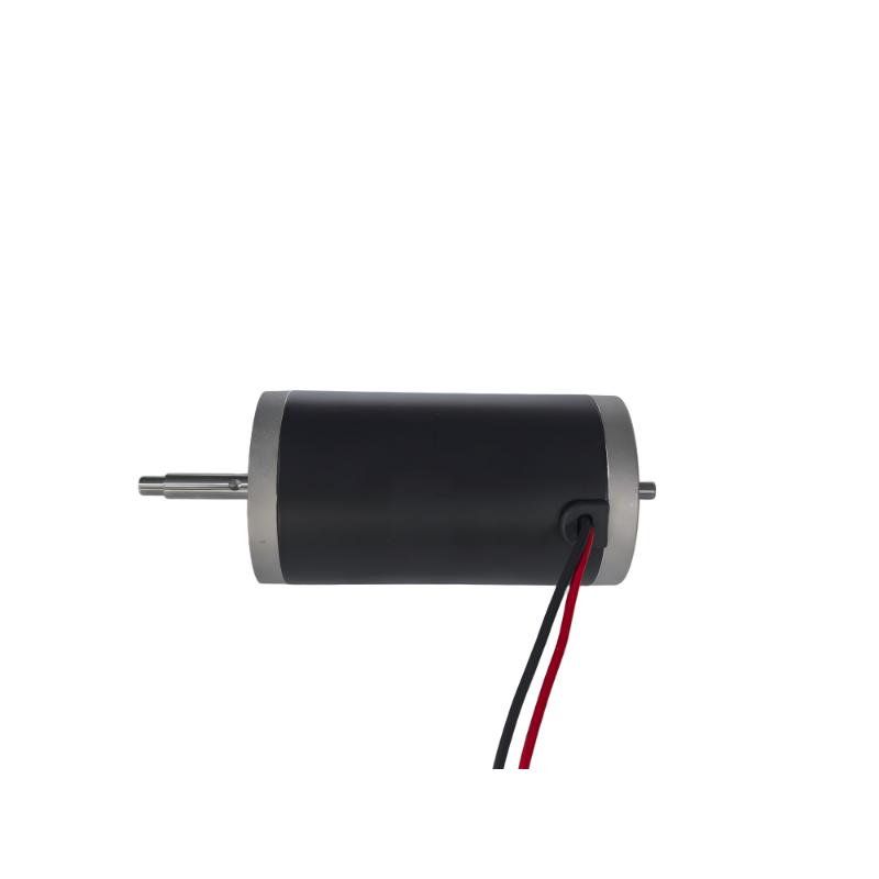
However, this technology comes with notable drawbacks. Physical brush wear demands routine maintenance and eventual replacement. Furthermore, the friction generates both electrical noise and physical sparks. Because of these traits, brushed options are ideal for cost-sensitive, intermittent-duty applications. For example, a standard Series 42 Brushed DC Motor is often entirely sufficient for basic automation tasks or non-critical consumer goods where continuous operation is not required.
Brushless motors replace the physical brushes with electronic commutation. This design shift offers massive performance upgrades. They deliver a higher power-to-weight ratio and require zero brush maintenance. They also operate at much higher efficiencies and are completely safe for environments containing flammable gasses since they do not spark.
The primary downside is complexity. BLDC systems require an Electronic Speed Controller (ESC) to function. This increases both upfront hardware costs and programming integration complexity. Despite this, BLDC technology is necessary for continuous-duty operations, high-reliability requirements, or compact device applications. A 60mm BLDC motor is highly suited for confined industrial spaces requiring long life cycles without routine maintenance access.
Feature | Brushed DC Motor | Brushless DC Motor (BLDC) |
|---|---|---|
Cost | Low initial cost | Higher initial cost (requires ESC) |
Maintenance | High (regular brush replacement) | Zero (no physical brushes) |
Lifespan | Moderate (limited by brush wear) | Long (limited only by bearings) |
Efficiency | Moderate (friction losses) | High (electronic commutation) |
Best For | Intermittent tasks, budget constraints | Continuous use, harsh environments |
Preventing premature failure requires a strict evaluation of environmental risks and authoritative safety standards before deployment.
Heat is the primary enemy of electric motors. You must carefully evaluate thermal thresholds using UL Temperature Class Ratings. For instance, a Class B rating indicates a maximum internal temperature limit of 130°C. Exceeding these limits destroys the internal insulation. Engineers follow a strict rule of thumb regarding heat: every 10°C increase above the rated maximum cuts motor lifespan in half. You must design adequate ventilation, select appropriate heat sinks, or limit the duty cycle to prevent thermal runaway.
Account for localized regulatory limits early in the design phase. Power draw limits can dictate your entire motor selection. For example, medical equipment operating in hospitals may need to strictly adhere to UL 15-Amp wall-draw limits. If your initial motor choice exceeds this current limit under heavy load, you will fail certification. Such strict power ceilings often force engineers to abandon low-efficiency options and choose highly efficient brushless systems paired with advanced gearing.
Balancing extreme physical size constraints with required performance outputs requires smart mechanical integration and gearing strategies.
Bigger motors generally output more power. When space is limited, you must evaluate a motor's true efficiency. Utilize the Motor Constant (Km) to evaluate a unit's power-to-torque ratio independently of its physical size. This constant helps you compare different motors fairly. A motor with a high Km will run cooler and generate more torque for a given amount of power. Evaluating this metric prevents you from selecting a bulky motor when a smaller, highly optimized alternative exists.
If your physical envelope rigidly restricts motor size, you can introduce gearheads to multiply torque and reduce speed. Gears allow a tiny motor to move heavy loads. You must compare gear efficiencies based on your needs:
Planetary Gears: These offer exceptionally high transmission efficiency and feature a compact inline footprint. They are perfect for battery-operated devices where saving power is crucial.
Spur Gears: Simple and cost-effective, but they consume more space and offer lower torque capacities.
Worm Gears: These provide native self-locking features, preventing back-driving when power is cut. However, they suffer from high friction loss, meaning they require more electrical power to do the same work.
Always specify industry-standard mounting flanges. Utilizing IEC34-7 standards ensures broad compatibility. For example, the B3 base mount relies on foot mountings, while the B5 outer flange mounts directly to the face of the machinery. Adhering to these standardized configurations ensures plug-and-play replacement down the line. It also provides vital supply chain redundancy, allowing you to source identical replacement motors from multiple vendors without redesigning your chassis.
Procurement decisions must look beyond the initial hardware price tag. Long-term performance considerations heavily influence ultimate project success.
Continuous operation degrades mechanical and electrical components significantly faster than intermittent use. If your application allows it, designing for an intermittent duty cycle yields major benefits. This approach allows a smaller, less expensive motor to perform the work and safely cool down between actuations. By carefully timing rest periods, you extend bearing life, preserve internal insulation, and reduce overall energy consumption.
You must factor in shifting global industrial regulations. Worldwide standards are aggressively pushing industries toward higher efficiency tiers. Moving toward IE4 efficiency class motors carries an initial premium at the time of purchase. However, the superior internal design minimizes energy losses. These highly efficient motors drastically reduce your operational energy overhead. In many 24/7 industrial applications, the initial price difference reaches a positive return on investment within just two years.
Dynamic loads create unique electrical challenges. Determine if your application involves heavy loads that require rapid reversing, sudden stopping, or holding against gravity. When you rapidly decelerate a spinning motor, it briefly acts as a generator, pushing energy back into the system. Standard controllers may not handle these regenerative energy loops safely. To prevent voltage spikes from frying your electronics, you must integrate specialized motor controllers equipped with external braking resistors to safely dissipate the excess energy as heat.
Selecting the ideal motion component requires a structured, multi-tier approach. You begin by sizing the exact torque and power requirements via objective physics. Next, you choose between brushed and brushless technology based on your duty cycle and budget. Finally, you finalize the mechanical integration using standard flanges and efficient gearing options.
Your next step should be practical validation. We highly recommend procuring off-the-shelf evaluation units. Bench-test these motors to validate their actual thermal behavior and verify their torque curves under real-world loads. This hands-on validation ensures perfect performance before you commit capital to a custom OEM production run.
A: Supplying a higher voltage proportionally increases the motor's rotational speed (RPM). While this might seem beneficial for gaining performance, it causes excessive heat generation within the coils. In brushed types, it leads to rapid, aggressive brush wear and dangerous arcing. If operated continuously at over-voltage, the internal insulation will melt, resulting in imminent thermal failure.
A: DC motors provide vastly superior starting torque compared to AC alternatives. They also offer much easier variable speed control simply by altering the input voltage. Furthermore, DC motors offer native, seamless compatibility with battery-operated and mobile applications, making them the default choice for robotics, portable medical devices, and automotive components.
A: First, ensure your power supply can actually deliver the necessary peak current during sudden acceleration. Second, verify that the motor's peak torque rating firmly exceeds the mechanical system's highest point of friction or inertia. If your current limits are strictly fixed by a battery or wall adapter, consider adding a planetary gear reducer to multiply the available torque.


