close
Choose Your Site
Global
Social Media
Views: 0 Author: Site Editor Publish Time: 2026-07-24 Origin: Site
Precision motion control relies on predictable, repeatable positioning. This mechanical reality makes the choice of actuator the most critical variable in any system design. Specifying the wrong motor architecture leads to compounding errors on the factory floor. Under-engineered systems suffer from missed steps and mechanical resonance that ruin product batches. Over-engineered closed-loop setups introduce unnecessary complexity and wiring overhead. Evaluating whether a DC Stepper Motor is the correct choice requires a deep understanding of its internal electromagnetics. You must understand how it processes digital pulses and the physical realities of its torque-speed curve in open-loop environments. This guide breaks down the mechanics, sizing, and field implementation of stepper motors to help you design reliable, high-performance motion control systems without overcomplicating the build.
Digital-to-Physical Translation: A DC stepper motor operates as a digital device, converting discrete electrical pulses from a driver into exact mechanical rotational steps without requiring feedback sensors.
High Holding Torque: Unlike standard DC motors, the static outer coils and rotating inner magnets of a stepper motor provide maximum torque at zero speed, ideal for holding loads in position.
The Hybrid Standard: The hybrid stepper motor is the industry standard for precision applications, combining the high step resolution of variable reluctance motors with the torque density of permanent magnet motors.
Application-Specific Sizing: Standardized form factors, such as the NEMA23 DC stepper motor, provide predictable mounting and baseline torque ratings, but final selection must account for load inertia and resonance zones.
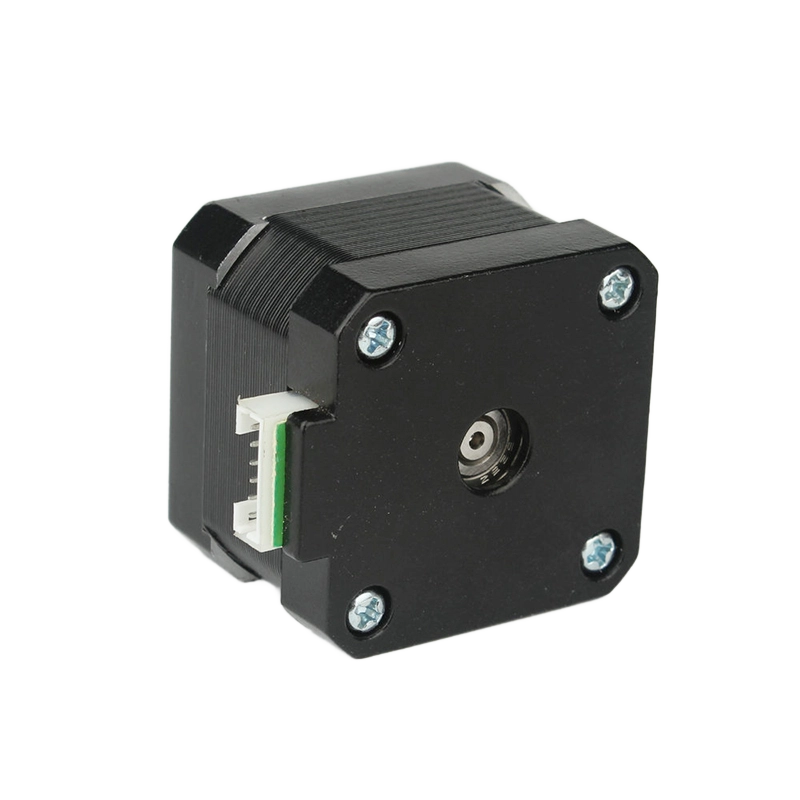
Engineers need to understand the internal mechanics and magnetic field transitions to predict how the motor will behave under varying loads and speeds. In standard brush DC motors, inner coils rotate while the outer permanent magnets stay static. In a DC stepper motor, this architecture is inverted. Static outer coils, known as the stator, surround a rotating inner magnetic core, the rotor. This design eliminates the need for mechanical brushes and commutators. It drastically reduces wear, eliminates brush dust, and cuts down on electrical noise that can interfere with sensitive control signals.
The physical construction consists of multi-phase stator windings and a magnetized rotor. Sequential energization of the stator coils creates an electromagnetic stepping field. This field forces the rotor to align with the active magnetic poles. The physical step angle determines the resolution of the movement. For example, a standard 200-step motor has a 1.8-degree step angle. The motor driver translates step-and-direction pulse trains from the controller into precise, phased current outputs that drive these coils.
Speed is controlled directly by the input pulse frequency measured in Hertz. A higher frequency equals a higher rotational speed in RPM. Driver time delays and pulse-rate tuning are necessary to manage rotor inertia during acceleration and deceleration phases. Stepper motors typically operate using an open-loop control architecture. No encoders or resolvers are required for basic operation. This provides simplicity benefits but carries the inherent risk of undetected positional errors if the motor stalls.
To prevent these errors, engineers must carefully profile the acceleration ramps. If you send a high-frequency pulse train to a resting motor, the rotor inertia will prevent it from catching up to the magnetic field, resulting in an immediate stall. Ramping the pulse frequency allows the rotor to stay synchronized with the stator field.
Understanding the primary architectures available for commercial and industrial motion control is essential for specifying the right component. The hybrid stepper motor features an axial permanent magnet combined with toothed rotor and stator caps. Physical offsets between stator and rotor teeth allow for fractional step angles, such as 0.9 or 1.8 degrees. The hybrid stepper motor is the dominant choice for CNC machines, robotics, and industrial automation due to its superior step resolution and dynamic torque capabilities.
Permanent Magnet motors use toothed or non-toothed cylindrical magnets. They offer larger step angles and lower torque. Variable Reluctance motors have no permanent magnets. They use soft-iron multi-toothed rotors and operate on the principle of minimum reluctance. Variable Reluctance motors offer high speed capability and zero detent torque but have significantly lower torque density compared to hybrid models.
Motor Type | Rotor Construction | Resolution | Holding Torque |
|---|---|---|---|
Permanent Magnet | Cylindrical Magnet | Low (7.5 to 15 degrees) | Moderate |
Variable Reluctance | Soft-Iron Toothed | Moderate | Low |
Hybrid | Magnet + Toothed Caps | High (0.9 to 1.8 degrees) | High |
When evaluating these options on the test bench, the hybrid design consistently outperforms the others in applications requiring precise positioning under load. The combination of the permanent magnet's flux and the variable reluctance tooth geometry creates a highly efficient magnetic circuit.
Translating motor specifications into real-world motion control outcomes requires analyzing the torque-speed curve. There is a strict inverse relationship between speed and torque in stepper motors. Winding inductance limits the current rise at high pulse frequencies. Because the current cannot reach its peak before the next step pulse arrives, the magnetic field weakens, leading to a sharp torque drop-off at higher RPMs.
Holding Torque is the stationary resistance the motor provides when fully energized. Pull-In Torque is the maximum load torque at which the motor can start or stop without losing steps. Pull-Out Torque is the maximum running torque the motor can sustain at a given speed before stalling.
Drivers subdivide full steps by proportioning current sinusoidally between adjacent stator phases. This technique is called microstepping. Microstepping increases positioning smoothness and apparent resolution. However, it drastically reduces incremental step torque. While the absolute holding torque remains high, the incremental dynamic stiffness drops significantly. Low-speed resonance zones and mid-band instability are inherent to stepper mechanics. Mechanical and electronic mitigation strategies include:
Installing mechanical elastomeric dampers on the rear shaft.
Utilizing viscous fluid couplings to absorb sudden inertial shifts.
Implementing microstepping to smooth out the discrete current steps.
Deploying advanced driver-side active damping algorithms that adjust phase timing.
Standardized sizing helps match motor capabilities to mechanical loads without custom machining. NEMA designations refer strictly to the mounting faceplate dimensions, not the internal electrical characteristics or motor length. The NEMA23 DC stepper motor is the standard mid-range workhorse for industrial automation. It offers an excellent balance of footprint and torque, typically ranging from 100 to 400 oz-in depending on the stack length.
The load-to-rotor inertia ratio is critically important for system stability. Ideally, keep this ratio below 10:1 for high performance, or below 5:1 for highly dynamic systems requiring rapid indexing. A severe mismatch leads to stalled motors, missed steps, and excessive settling times at the end of a move. When the load inertia is too high, the motor acts like a torsional spring, oscillating around the final target position before coming to rest.
Inertia Ratio (Load:Rotor) | System Dynamics | Application Suitability |
|---|---|---|
1:1 to 3:1 | Extremely crisp response, zero ringing | High-speed pick and place, optical inspection |
4:1 to 10:1 | Stable, manageable resonance | General CNC routing, conveyor indexing |
Over 10:1 | Sluggish, high risk of stalling and ringing | Slow, continuous rotation only (avoid if possible) |
Establishing the technical boundaries of stepper technology compared to alternatives helps in making the right choice on the engineering floor. Specify a stepper motor for applications requiring high torque at low speeds, generally under 1,000 RPM. They are ideal for projects where open-loop predictability is sufficient and mechanical binding is unlikely. They also suit systems requiring high holding torque without continuous power draw fluctuations, completely avoiding the "hunting" behavior of servos at a standstill.
Closed-loop servos are mandatory for applications demanding high torque at high speeds, typically above 1,000 to 3,000 RPM. They are required for systems where dynamic, unpredictable load changes occur during the motion profile. They are also necessary in strict compliance environments where absolute position verification is a safety or regulatory requirement, such as medical device manufacturing or heavy robotic arms.
Addressing the common failure modes of stepper-driven systems ensures long-term reliability. Exceeding the pull-out torque causes the rotor to fall out of step synchronization with the rotating stator field, resulting in missed steps and ruined alignment. Mitigate this by implementing conservative safety margins in torque sizing. Typically, a 50-100% over-specification is standard practice. Program gradual acceleration and deceleration ramping in the motion controller to handle inertial loads safely.
Stepper motors are constant-current devices. They draw full current even at a standstill to maintain holding torque, leading to significant thermal output. Motor cases can easily reach 80 degrees Celsius during normal operation. Mitigate this risk by utilizing driver features like idle-current reduction, which drops the holding current by 50% when the motor is stopped for more than a few milliseconds. Ensure proper heat sinking by mounting the motor to a large aluminum frame and evaluate duty cycles carefully during the design phase.
A stepper motor provides a highly reliable, digital actuator for precision motion control, provided the application operates within its specific torque-speed limitations. Base your final selection on the required holding torque, the maximum operational speed, and the load-to-rotor inertia ratio. The hybrid architecture, particularly in standard sizes like the NEMA23, will satisfy the majority of mid-tier automation requirements.
Calculate the exact load inertia for your specific mechanical drivetrain.
Consult manufacturer torque-speed curves to verify pull-out torque at your target RPM.
Prototype the system with a microstepping driver to evaluate resonance and adjust tuning parameters.
Implement a 50% torque safety margin to prevent missed steps during unexpected load spikes.
A: In a standard brush DC motor, the inner coils rotate while the outer permanent magnets remain static. In a stepper motor, the architecture is inverted: the static outer coils surround a rotating inner magnetic core.
A: Stepper motors lose torque at high speeds because winding inductance limits the rate at which current can rise. At high pulse frequencies, the current cannot reach its maximum level before the next step, reducing the magnetic force.
A: Open-loop means the motor operates without feedback sensors like encoders. The controller sends step pulses to the driver, assuming the motor executes them correctly, but there is no verification of the actual rotor position.
A: A hybrid stepper motor combines features of both permanent magnet and variable reluctance motors. It uses an axial permanent magnet and toothed rotor caps, allowing for much finer step angles and higher torque.
A: Yes, a hybrid stepper motor can be used in a closed-loop system by adding an encoder to the rear shaft. This provides position feedback to the controller, preventing missed steps and improving overall system reliability.
A: The choice depends on torque requirements and physical space. NEMA17 motors are smaller and suit lighter loads. NEMA23 motors offer higher torque and are better for industrial automation and heavier CNC applications.
A: A stepper motor misses steps when the required load torque exceeds the motor's pull-out torque at a given speed. This can be caused by rapid acceleration, mechanical binding, or severe load-to-rotor inertia mismatches.