
close
Choose Your Site
Global
Social Media

Views: 0 Author: Site Editor Publish Time: 2026-07-01 Origin: Site


Choosing a stepper motor requires more than picking a generic component off a shelf. It represents a critical engineering trade-off between reliable torque delivery and overall system efficiency. Getting this specification wrong creates severe mechanical and operational issues down the line. Undersizing your motor inevitably leads to missed steps. You will face stalled loads, ruined workpieces, and severe positional inaccuracy during rapid movements. Conversely, oversizing wastes valuable resources and space. It adds unnecessary mass to your moving parts. This excess mass increases system inertia and complicates thermal management significantly.
This guide serves as your technical decision-making framework. We will help you match precise mechanical load requirements to the correct NEMA Stepper Motor form factor. You will learn how to size your motor perfectly for your exact application. You will avoid over-engineering the solution while guaranteeing reliable performance across your entire operational speed range.
"NEMA size" defines the mounting faceplate dimensions, not the motor’s length, electrical characteristics, or total torque output.
Selecting the right motor requires calculating dynamic torque needs at your target operating speed, not just relying on static holding torque.
Always factor in a 20% to 30% safety margin to account for mechanical friction and system degradation over time.
Motor length (stack size) within a specific NEMA category allows for torque scaling without altering your mounting footprint.
We must first clarify the NEMA designation. The National Electrical Manufacturers Association (NEMA) established a standardized framework for the industry. This standard simply dictates the physical mounting interface. It specifies the faceplate size and the screw hole spacing. It does not dictate electrical power limits. It does not specify coil configurations or internal magnet strengths. Two motors sharing the exact same NEMA rating can possess vastly different performance profiles.
The calculation behind the naming convention remains straightforward. The NEMA number reflects the motor's faceplate dimension in inches multiplied by 10. For instance, a NEMA 17 motor features a 1.7-inch by 1.7-inch faceplate. A NEMA 23 motor features a 2.3-inch faceplate. This naming rule applies consistently across all standard sizes, making initial dimension planning predictable.
Engineers must debunk the "bigger is always stronger" myth. Many people assume larger NEMA sizes automatically provide more torque. While larger physical sizes generally hold larger rotors, crucial nuances exist. A long-stack motor in a smaller NEMA class can sometimes outperform a short-stack motor in a larger class. Stack length determines the internal magnet volume. A triple-stack NEMA 17 might output considerably more torque than a single-stack NEMA 23.
Choosing a NEMA size is primarily about locking in mechanical constraints. You establish your mounting footprint early in the design phase. Once you machine your brackets and set your bolt patterns, changing NEMA sizes requires physical rework. Selecting the correct faceplate size upfront grants you flexibility later. You can swap stack lengths to fine-tune torque without altering your custom mounting hardware.
You must clearly differentiate between holding torque and dynamic torque. Holding torque defines the rotational force required to hold a load stationary. Dynamic torque defines the actual force required to move the load. Many specification sheets highlight holding torque prominently because the static number looks impressive. We warn against using holding torque as your sole selection criteria. Moving a physical mass requires overcoming static friction and system inertia, relying entirely on dynamic torque.
Stepper motors inherently lose torque as speed increases. Electrical current takes time to fully charge the motor coils. As RPM increases, the coils have less time to charge before the next step sequence. You must evaluate the speed-torque curve provided by the manufacturer. Plot your application's required speed directly against this specific curve. A motor showing massive holding torque might drop off completely at your target operating RPM.
Consider the concept of inertia matching carefully. You must match the rotor's internal inertia to the external load's inertia. Engineers generally target a 1:1 to 1:10 ratio. A massive load attached to a tiny rotor will struggle to accelerate smoothly. Proper inertia matching ensures stable acceleration profiles. It also prevents destructive resonance vibrations at mid-range operational speeds.
Always calculate a generous safety margin. We highly recommend adding a strict 20% to 30% torque safety buffer. Real-world physical variables degrade performance over time. Bearing wear increases mechanical friction. Extreme temperature changes affect magnetic flux density within the motor. Microstepping also introduces apparent torque loss. A safety buffer protects your machine from stalling under these unpredictable conditions.
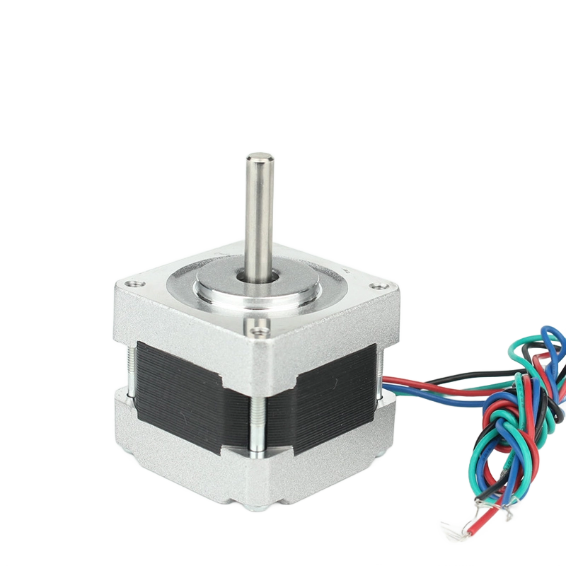
Understanding specific category parameters helps narrow down your choices. Let's examine the standard form factors used across modern automation systems.
The NEMA11 stepper motor represents compact precision. It features a ~1.1-inch faceplate (approximately 28mm). Engineers specify this size for tightly space-constrained applications. You frequently find them inside optical instruments, medical pipettes, and micro-robotics. The primary limitation involves its very low torque output. You need highly efficient drivetrains to use it effectively. Avoid high-friction leadscrews when deploying this compact motor.
The NEMA17 stepper motor serves as the undisputed industry workhorse. It features a ~1.7-inch faceplate (approximately 42mm). You see this motor powering desktop 3D printers globally. It drives small CNC routers, laser engravers, and light automation equipment. It offers the absolute best balance of widespread availability and mid-range torque. It handles moving loads under 5 lbs highly effectively.
NEMA 23 and 24 form the mid-range power category. These motors feature ~2.3-inch or ~2.4-inch faceplates. They comfortably power medium-duty CNC machines. They drive heavier industrial linear actuators and conveyor systems. They represent the logical upgrade path when NEMA 17 motors drop steps under heavy operational load.
The NEMA34 stepper motor handles heavy-duty automation tasks. It features a massive ~3.4-inch faceplate (approximately 86mm). You will find it installed on heavy industrial machinery. It runs large-format CNC mills, automated packaging lines, and heavy material handling robots. You must consider the surrounding infrastructure carefully. This motor requires significant power supplies. You need robust motor drivers to handle the high current demands. You must also use reinforced metal mounting brackets. High rotational mass and intense vibration will quickly bend weak mounts.
NEMA Size | Faceplate Dimension | Typical Shaft Diameter | Best Use Case |
|---|---|---|---|
NEMA 11 | 1.1 inches (28mm) | 5mm | Space-constrained optical instruments |
NEMA 17 | 1.7 inches (42mm) | 5mm | 3D printers, light automation |
NEMA 23 | 2.3 inches (57mm) | 6.35mm / 8mm | Medium CNC routers, actuators |
NEMA 34 | 3.4 inches (86mm) | 12.7mm / 14mm | Heavy industrial machinery |
Stack length determines the physical depth of the motor housing. Selecting a double or triple-stack motor allows engineers to drastically increase torque capacity. You achieve this while maintaining the exact same NEMA mounting footprint. However, there is a notable engineering trade-off. Longer motors inherently possess higher coil inductance. High inductance limits high-speed performance. The magnetic fields take much longer to build up and collapse. A short-stack motor spins significantly faster without losing as much torque.
Stepper motors naturally run hot during normal operation. External casing temperatures often reach 80°C (176°F). We acknowledge that this heat generation is typical for constant-current drives. Larger NEMA sizes dissipate heat better due to their increased surface area. However, they also draw more current and generate more raw heat internally. Ensure proper ventilation around your mounting brackets. Use thick aluminum mounts to act as effective thermal heat sinks.
You must address the impact of motor weight on moving system dynamics. Motor weight significantly impacts any moving axes. Imagine mounting a heavy NEMA 34 directly onto a moving gantry rail. It introduces massive mechanical momentum. You will need even more torque just to accelerate and decelerate the motor's own physical mass. Keep the heaviest motors stationary whenever possible. Transfer their power via timing belts, rack and pinions, or long leadscrews to keep the moving carriage light.
Follow this step-by-step selection logic to guarantee a correct match for your design:
Calculate the maximum dynamic torque needed at your specific target RPM.
Apply the strict 20-30% safety margin to account for long-term system degradation.
Identify the smallest NEMA size that meets the torque requirement to save weight and space.
Choose the appropriate stack length within that specific NEMA size footprint.
Next, run a thorough driver compatibility check. A stepper motor performs only as well as its connected driver. Ensure the chosen motor's rated current (measured in Amps) aligns with the selected stepper driver's maximum capabilities. Check the phase inductance carefully. Supplying too little voltage to a high-inductance motor ruins its high-speed performance profile and leads to stalling.
Finally, follow our strict prototyping advice. We highly recommend purchasing two variations for initial testing. Buy a standard-stack and a long-stack variation of your chosen NEMA size. Perform physical load testing in your actual machine environment. Verify positional accuracy and heat generation under maximum load. Do this practical testing before finalizing any large-volume procurement order.
Sizing a stepper motor remains a multi-dimensional engineering decision. You must constantly balance torque output, target operational speed, and physical footprint constraints. Never evaluate a motor based on static holding numbers alone. Always refer to dynamic speed-torque curves to understand real-world capabilities.
Conservative sizing protects your projects against costly late-stage redesigns. Incorporating reasonable safety margins ensures reliable long-term operation under varying conditions. Simultaneously, avoiding massive oversizing protects your system's agility. It keeps moving masses low, prevents mechanical resonance issues, and avoids unnecessary structural stress.
Take decisive action by consulting specific manufacturer speed-torque curves today. Plot your exact RPM requirements directly onto those charts. If you design complex multi-axis setups, contact an application engineer. They will help verify your inertia matching calculations and confirm your hardware selections to ensure flawless automation.
A: Not without mechanical modifications. The mounting holes and shaft diameters are different. You must design adapter plates or change the mounting bracket entirely to accommodate the larger faceplate and bolt pattern.
A: No. Often, larger motors have higher inductance, which actually limits their high-speed performance compared to smaller motors. Larger motors are built for torque, not necessarily RPM.
A: You will waste power, increase system weight, introduce aggressive resonance/vibration, and overspend on larger power supplies and high-amperage motor drivers unnecessarily.
A: High microstepping (e.g., 1/16 or 1/32) reduces incremental holding torque. If your application relies heavily on microstepping for smooth motion, you may need a slightly larger motor to compensate for the perceived torque loss at the microstep level.


