close
Choose Your Site
Global
Social Media
Views: 0 Author: Site Editor Publish Time: 2026-09-16 Origin: Site
Selecting a motor based solely on basic voltage and RPM specifications often leads to system failure, thermal throttling, or inefficient power draw under real-world loads. Transitioning to or selecting a brushless architecture requires balancing power density, electronic speed controller (ESC) compatibility, and specific torque-to-speed ratios without over-speccing the system and inflating costs. Engineers must look beyond the spec sheet to understand how a motor behaves under dynamic conditions on the factory floor or in the field.
This guide breaks down the technical evaluation criteria, architectural trade-offs, and implementation realities required to specify the exact motor for your operational parameters. You will learn how to match load profiles to motor types, navigate thermal constraints, and select the right commutation strategy for your specific application. We focus on practical engineering realities, bypassing theoretical fluff to deliver actionable integration strategies.
KV Rating Dictates Application: The KV rating (revolutions per volt) must align with your required RPM and torque; low KV is essential for high torque, while high KV serves high-speed, low-torque needs.
System-Level Voltage Matters: Standardizing on specific voltages (like a 48V architecture) directly impacts current draw, wire sizing, and overall thermal management.
Control Complexity is Mandatory: Unlike brushed alternatives, brushless motors require precise electronic commutation (sensored or sensorless), factoring heavily into total system cost and integration time.
Form Factor vs. Thermal Limits: High power density in smaller footprints requires aggressive thermal mitigation to maintain the 65–80%+ efficiency ratings typical of brushless systems.
You must analyze when to choose a brushless architecture over traditional brushed alternatives. Brushless designs excel in applications requiring high reliability, continuous high-speed operation, and spark-free environments. The absence of physical brushes eliminates mechanical wear and electrical arcing. This makes them ideal for volatile environments or systems requiring zero maintenance downtime. We see this constantly in industrial automation where replacing worn brushes causes unacceptable line stoppages.
When comparing performance to stepper motors for positioning applications, evaluate the performance benefits. Closed-loop brushless control offers superior high-speed torque and efficiency. Open-loop stepper systems provide simplicity and excellent holding torque at zero speed but suffer from resonance and missed steps at higher velocities. Physical construction also differs significantly. Brushless designs place permanent magnets on the rotor and windings on the stator. This configuration shifts thermal management challenges directly to the outer casing, requiring different cooling strategies than brushed motors.
Consider the specific control requirements of your system. Stepper motors operate via discrete steps, making them easy to command for basic positioning. However, a Brushless DC Motor paired with a high-resolution encoder provides fluid, continuous motion with absolute position feedback. This closed-loop system corrects for external disturbances instantly, a mandatory feature for precision robotics and CNC machinery.
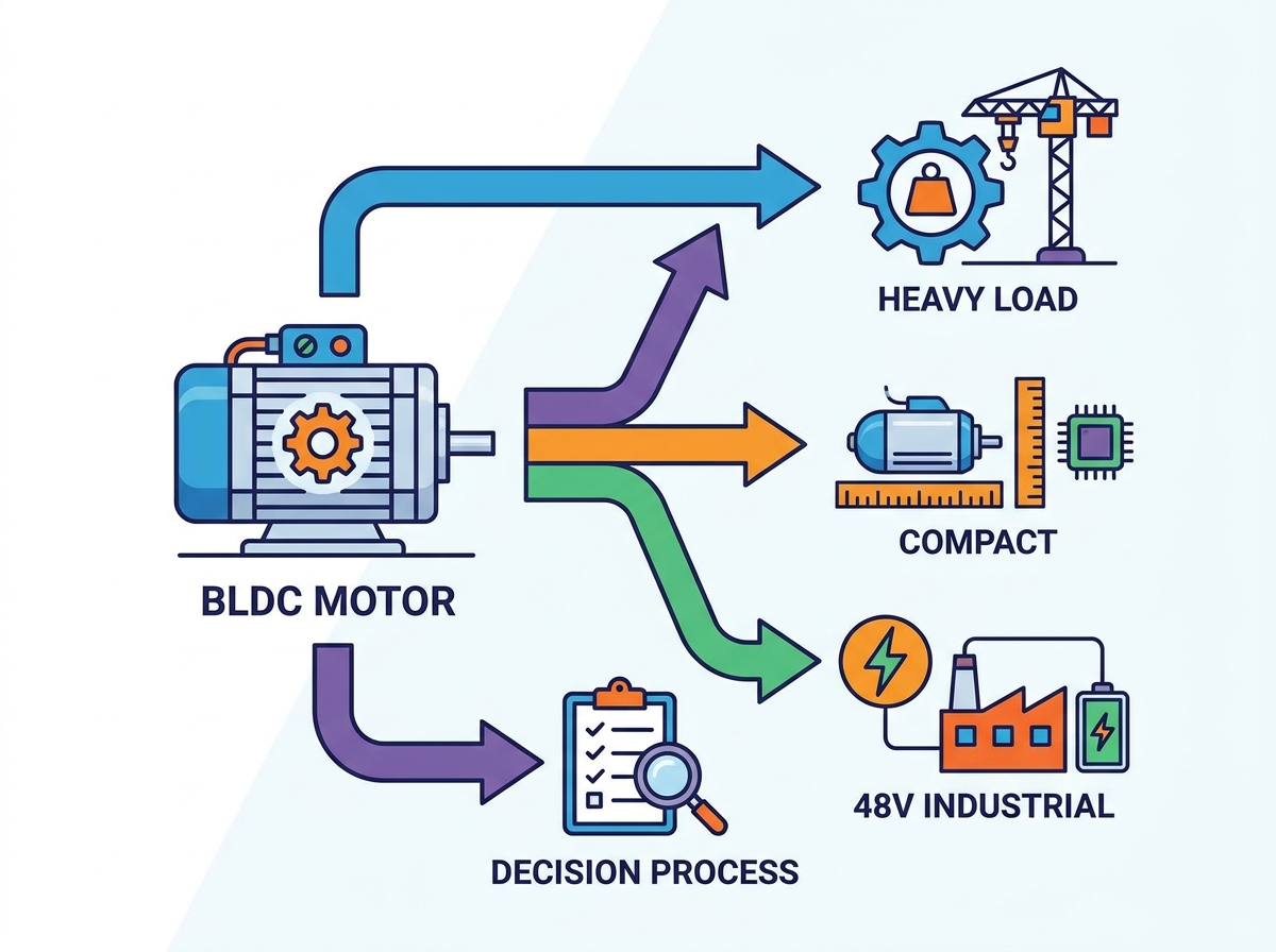
Identifying the difference between holding torque, peak operating torque, and continuous operational torque is critical. Holding torque keeps a load stationary. Peak torque handles momentary spikes during acceleration. Continuous torque defines the maximum load the motor can sustain indefinitely without overheating. Evaluating requirements for a heavy load motor involves calculating starting inertia, friction coefficients, and dynamic load changes during operation.
You must define acceptable current draw limits during peak load scenarios. Exceeding these limits leads to ESC burnout or demagnetization of the rotor. Implement right-sizing strategies carefully. Sometimes, using a smaller, less powerful motor prevents excessive current draw. This approach stops the system from overloading power supplies or tripping battery protection circuits during unexpected mechanical binds.
Engineers often make the mistake of sizing a motor based solely on peak torque requirements. If a mechanism only requires peak torque for 500 milliseconds during initial acceleration, sizing the continuous rating for that peak value results in a massively oversized, heavy, and inefficient system. Instead, calculate the Root Mean Square (RMS) torque over the entire duty cycle to find the correct continuous rating.
The KV rating defines the RPM a motor spins per volt applied under no-load conditions. It shares an inverse relationship with torque. A high KV motor spins fast but delivers less torque per amp. A low KV motor spins slower but generates significant torque. You must calculate the theoretical no-load speed versus the actual loaded speed. Real-world loads typically reduce the theoretical RPM by 15 to 20 percent.
Ultra-low RPM applications present unique challenges. Operating at 1 to 2 RPM is highly inefficient for standard brushless designs. Relying solely on a low KV rating is insufficient for these extreme low-speed tasks. You must integrate mechanical reduction to allow the motor to spin in its optimal efficiency band while delivering the required low-speed output.
When selecting the KV, always factor in the maximum voltage of your power supply fully charged versus fully depleted. A system designed to hit a specific RPM at 24V will fall short if the battery pack sags to 21V under load. Build a 10 to 15 percent voltage headroom into your KV calculations to ensure consistent speed across the entire discharge cycle.
Assess the physical envelope of your project early in the design phase. The space-saving benefits of a compact motor allow for sleeker product designs and reduced overall weight. However, you must determine the viability of this compact design against the risk of localized heat accumulation. Tight spaces restrict airflow, causing rapid temperature spikes under heavy loads.
Evaluate mounting configurations carefully. Ensure the chassis can act as a heatsink if airflow is limited. Check shaft lengths and bearing load capacities. Radial loads from belts or axial loads from helical gears can quickly destroy undersized bearings in smaller motor frames.
Consider the routing of phase wires and sensor cables. In tight enclosures, stiff silicone wires require adequate bend radii to prevent stress on the internal stator connections. Failure to account for wire routing often leads to chafed insulation and catastrophic phase-to-phase shorts against the metal chassis.
Inrunner motors feature a rotor that spins inside the stator. This design offers higher RPM capabilities and better heat dissipation. The heat-generating windings connect directly to the outer casing, making external cooling highly effective. Inrunners typically produce lower torque, making them ideal for ducted fans or high-speed machinery.
Outrunner motors feature an outer shell that spins around the internal stator. This configuration delivers lower RPM but significantly higher torque generation due to a larger moment arm. The spinning outer bell makes them harder to cool in enclosed spaces. Outrunners often serve as direct-drive solutions for heavy loads.
Feature | Inrunner Motor | Outrunner Motor |
|---|---|---|
Rotor Position | Inside the stator | Outside the stator |
RPM Capability | High (often >30,000 RPM) | Low to Medium (<10,000 RPM) |
Torque Output | Low to Medium | High |
Cooling Efficiency | Excellent (outer casing acts as heatsink) | Poor in enclosed spaces |
Inertia | Low (fast acceleration) | High (smooth operation) |
Typical Use Case | High-speed pumps, fans, geared drives | Direct-drive robotics, drones, gimbals |
Choosing between these two architectures dictates your entire mechanical drivetrain. If you select an inrunner for a high-torque application, you must incorporate a gearbox. If you select an outrunner, you might achieve direct drive, but you must ensure the spinning outer bell has clearance and won't ingest debris from the operating environment.
Sensored commutation utilizes Hall Effect sensors to detect rotor position. This is required for applications needing high torque at zero or very low RPM. It provides precise rotor position data, ensuring smooth startup under heavy loads. However, it adds wiring complexity and introduces potential points of failure in harsh, dusty, or wet environments.
Sensorless commutation relies on measuring back-EMF generated by the spinning motor. It is ideal for continuous, high-speed applications like pumps, fans, and drones. This method reduces wiring and increases environmental robustness. The primary drawback is cogging or stuttering at startup, as the ESC cannot detect the rotor position until the motor is already moving.
Evaluate Startup Load: If the motor starts under a heavy physical load (like an electric vehicle on a hill), sensored commutation is mandatory.
Assess Environmental Hazards: If the motor operates submerged in oil or exposed to heavy vibration, sensorless designs eliminate fragile Hall sensors and thin gauge wiring.
Consider Hybrid Controllers: Many modern ESCs use sensored mode for startup and seamlessly transition to sensorless mode at higher RPMs to maximize efficiency.
Check Wiring Constraints: Sensored motors require at least five additional wires (Power, Ground, Hall A, Hall B, Hall C). Ensure your slip rings or cable carriers can accommodate this bundle.
Analyze the relationship between voltage, current, and heat. Heat generation scales with the square of the current. Increasing system voltage allows you to achieve the same power output at a lower current. Evaluate the benefits of utilizing a 48V industrial BLDC motor for high-power applications. This higher voltage keeps current draw manageable and reduces cable gauge requirements.
Match motor voltage ratings carefully with available battery chemistries or industrial power supplies. Account for voltage sags under high load. A power supply that drops voltage during peak demand will cause the motor to lose RPM and potentially stall, leading to massive current spikes.
High voltage systems also improve ESC efficiency. Switching high currents generates significant heat in the MOSFETs of the motor controller. By doubling the voltage and halving the current for a given power target, you drastically reduce the thermal load on the control electronics, extending their lifespan and reliability.
Map the motor's efficiency curve to your project's nominal operating point. Advertised efficiency ratings of 65 to 80 percent are not linear. Efficiency drops significantly under stall conditions, partial throttle, or improper load matching. Operating outside the peak efficiency zone converts wasted energy directly into heat.
Compare power density limitations. Brushless designs offer leading power density, second only to universal motors. However, this high power density requires active management of heat dissipation. A motor may boast high peak power, but without adequate cooling, its continuous power rating will be severely limited.
Always request the motor's dynamometer charts from the manufacturer. Look at the efficiency island. You want your continuous operating torque and RPM to sit dead center in the highest efficiency contour. If your nominal load pushes the motor into the 50 percent efficiency range, you will spend more time managing heat than doing useful mechanical work.
Determine when to pair a higher-speed motor with a planetary, spur, or worm gearhead. Attempting to direct-drive a heavy, low-speed load often results in extreme inefficiency and overheating. Gearing allows the motor to spin in its optimal high-efficiency RPM band while delivering the necessary torque at the output shaft.
Calculate mechanical losses introduced by gearboxes. Planetary gears offer high torque density but introduce friction. Compare these mechanical losses against the electrical efficiency gained by running the motor at its ideal speed. Often, a geared system consumes less overall power than a struggling direct-drive setup.
Planetary Gearboxes: Excellent for high torque in a compact inline form factor. Expect 80 to 90 percent mechanical efficiency depending on the number of stages.
Worm Drives: Provide high reduction ratios and self-locking capabilities, but suffer from terrible mechanical efficiency (often below 60 percent).
Spur Gears: Simple, highly efficient, and easy to maintain, but require parallel shaft arrangements that consume more lateral space.
Belt Drives: Great for isolating the motor shaft from shock loads and providing quiet reduction, but require tensioning mechanisms and regular maintenance.
Factor in the complexity of the motor controller, which often dictates the success of the integration. Brushless motors require sophisticated electronics to handle commutation. You must evaluate firmware requirements, such as Field Oriented Control (FOC) versus Trapezoidal commutation, and the associated development time.
FOC provides smooth, silent operation and maximizes efficiency by keeping the magnetic fields perfectly aligned. However, tuning FOC parameters (PID loops, observer gains) requires significant engineering effort. Trapezoidal control is simpler to implement and robust but generates more acoustic noise and torque ripple at low speeds.
Assess the elimination of brush wear and its impact on maintenance schedules. Brushless motors theoretically run forever, but practical realities introduce new limiting factors. Identify these new limits: bearing degradation, insulation breakdown, and demagnetization from excessive heat.
Bearings usually fail first. Specify sealed, high-quality bearings if the motor operates in dusty environments. Monitor operating temperatures closely. Neodymium magnets lose their magnetic flux permanently if pushed past their Curie temperature, instantly turning a high-performance motor into a useless paperweight.
Over-propping or over-loading the motor leads directly to thermal runaway. Excessive heat breaks down the enamel insulation on the windings, causing internal short circuits. Extreme temperatures also cause permanent magnet damage, permanently reducing the motor's torque capacity. A damaged stator cannot be easily repaired in the field.
Mitigate these risks by implementing active cooling solutions. Use heat sinks, forced air, or liquid cooling jackets for high-stress environments. Program strict current-limiting parameters within the ESC. These software limits prevent the motor from drawing destructive amounts of current during unexpected mechanical jams.
Thermal potting compounds offer another layer of protection. Encapsulating the stator windings in a thermally conductive epoxy improves heat transfer to the outer casing and protects the delicate copper wires from heavy vibration and moisture ingress.
High-frequency switching in the ESC generates significant electromagnetic interference. This EMI easily disrupts nearby sensors, microcontrollers, or communication lines. Unshielded motor wires act as antennas, broadcasting switching noise throughout your system architecture.
Mitigate EMI through proper shielding techniques. Use twisted-pair wiring for phase leads to cancel out magnetic fields. Keep motor wires as short as possible. Ensure your system complies with industrial EMC standards to guarantee reliable operation in complex electrical environments.
Install ferrite chokes on the power leads between the battery and the ESC. Route sensitive signal cables, like encoder wires or CAN bus lines, far away from the high-current motor phase wires. Ground the motor casing directly to the main chassis to provide a safe path for stray currents.
Define your required continuous torque and operating voltage before looking at physical motor sizes.
Select a KV rating that places your nominal operating speed at roughly 80 percent of the theoretical no-load RPM.
Procure two to three candidate motors with varying KV ratings to conduct physical bench testing under simulated loads.
Validate thermal performance and heat dissipation strategies before finalizing your mechanical chassis design.
Program hard current limits into your ESC firmware to protect the motor from unexpected mechanical stalls.
A: Multiply your system voltage by the KV rating to find the theoretical no-load RPM. For loaded applications, target a no-load RPM about 15 to 20 percent higher than your required operating speed. This buffer accounts for the natural RPM drop induced by mechanical loads and friction.
A: Direct-driving a brushless motor at 1 to 2 RPM is highly inefficient and causes stuttering. For ultra-low speeds, you must use a sensored motor combined with a high-ratio mechanical gearbox. This allows the motor to spin efficiently while delivering slow, precise output.
A: Stuttering, or cogging, occurs in sensorless systems. The ESC cannot determine the exact position of the rotor when stationary. It sends blind pulses to get the motor spinning enough to read the back-EMF. Sensored motors eliminate this issue entirely.
A: Overheating under light loads usually indicates a mismatch between the motor's KV rating and the system voltage, or incorrect ESC timing settings. Running a high KV motor at partial throttle forces the ESC to work harder, generating excess heat in both components.
A: No. Fans and pumps are continuous, high-speed applications that do not require high starting torque. A sensorless motor is perfectly suited for these tasks. It reduces wiring complexity and increases overall system reliability by eliminating fragile sensor components.
A: Voltage sag reduces the maximum RPM the motor can achieve. If the power supply cannot maintain voltage under heavy current draw, the motor slows down. This forces the ESC to increase current to maintain power, leading to rapid overheating and potential system failure.