close
Choose Your Site
Global
Social Media
Views: 0 Author: Site Editor Publish Time: 2026-07-19 Origin: Site
Commercial off-the-shelf motors often fall short when you design specialized hardware, robotics, or smart home products. Standard units force engineers to compromise on form factor. You end up settling for suboptimal torque delivery or over-engineering surrounding components just to fit generic motor dimensions. When standard catalogs fail your exact application requirements, transitioning to a custom engineered solution becomes necessary.
Choosing the wrong custom manufacturing partner carries high stakes. A poorly vetted vendor causes delayed time-to-market. You risk field failures from inadequate thermal dissipation. You also face escalating unit costs stemming from poor Design for Manufacturing (DFM) practices. Hardware developers need a partner capable of translating complex electromechanical requirements into repeatable, high-yield production runs.
Evaluating custom motor manufacturers requires a structured framework. You must scrutinize the vendor's core engineering capabilities, prototyping speed, quality control infrastructure, and supply chain reliability. By systematically assessing these operational pillars, engineering teams secure a manufacturing partner that delivers precise mechatronic integration while mitigating production risks.
Engineering Alignment: A viable custom manufacturer must offer robust co-engineering and DFM support, not just build-to-print services.
Magnet & Form Factor Expertise: Vendor selection should hinge on their proven ability to produce specific configurations (e.g., sintered vs. bonded magnets) at your required diameter and length.
Scalability vs. Prototyping: The ideal partner bridges the gap between low-volume custom prototyping and high-yield mass production without compromising quality.
Risk Mitigation: Strict adherence to ISO standards, end-of-line testing, and clear IP protection protocols are non-negotiable for custom component sourcing.
The tipping point for custom engineering occurs when standard form factors actively hinder product development. Off-the-shelf motors utilize standardized shaft lengths, generic mounting patterns, and baseline insulation classes designed for broad market appeal. When an application demands non-standard shaft modifications, specific ingress protection (IP) ratings for harsh environments, or extreme ambient temperature resilience, standard units become liabilities. Success criteria for custom integration hinge on achieving exact mechanical fitment and optimized electromagnetic performance without relying on bulky adapters or external cooling mechanisms. You need a motor that fits the product, not a product built around a motor.
Consider the spatial constraints in modern robotics. Joints require high torque density in flat, pancake-style profiles. Standard cylindrical motors simply do not fit. Custom engineering allows you to specify the exact outer diameter and stack length. You can dictate the mounting hole patterns to align perfectly with your custom gearboxes. This level of mechanical integration eliminates the need for transition plates, reducing overall assembly weight and mechanical complexity.
Early-stage developers and hardware startups face unique integration hurdles. Designing smart home appliances, specialized mechatronics, or compact medical devices requires components that seamlessly blend into constrained enclosures. These organizations must balance the need for low-volume entry points during initial market testing with scalable production paths. A custom Brushless Motor allows startups to differentiate their hardware through superior acoustics, higher efficiency, and exact form-factor matching, provided the manufacturer supports flexible scaling.
Startups often operate on tight funding runways. They cannot afford multiple failed prototyping iterations. Therefore, the chosen manufacturing partner must provide accurate simulation data before cutting any metal. Electromagnetic FEA (Finite Element Analysis) helps predict motor performance, cogging torque, and thermal behavior. When a vendor provides this data upfront, it builds confidence that the first physical prototype will closely match the required specifications, saving both time and capital.
Custom tooling introduces upfront Non-Recurring Engineering (NRE) costs. Machining custom shafts, developing specific winding jigs, and creating unique stamping dies require initial capital investment. However, these upfront expenses must be weighed against long-term returns. Custom motors optimize electrical efficiency, reducing battery size requirements in portable devices. They also minimize assembly time by integrating mounting features directly into the motor housing. Exact torque-speed matching ensures the motor operates at its peak efficiency point, reducing energy waste and extending product lifespan.
Let us break down the NRE components. Custom stamping dies for stator laminations represent a significant investment. If your design requires a unique slot-to-pole combination to minimize cogging torque, standard laminations will not work. You must pay for the tooling. However, this custom lamination design might increase motor efficiency by five percent. In a battery-powered device, that efficiency gain translates to longer runtimes, allowing you to use a smaller, lighter battery pack. The savings on the battery pack often offset the motor NRE costs over the first production run.
Modern hardware rarely relies on a bare motor. Applications frequently demand custom gearboxes for torque multiplication, specialized high-resolution encoders for precise position feedback, or integrated motor controllers to save PCB space. Commercial vendors typically supply these as disparate components, forcing the OEM to manage complex assembly tolerances. A capable custom manufacturer provides a unified mechatronic assembly, ensuring the gearmotor integration is factory-aligned, tested as a single system, and optimized for the specific load profile.
When you source the motor, encoder, and gearbox from different vendors, you assume the integration risk. If the encoder optical disk rubs against the motor housing due to stack-up tolerances, you own that failure. By partnering with a manufacturer capable of delivering the complete mechatronic assembly, you shift the integration responsibility to them. They must guarantee that the final assembled unit meets the required backlash, positioning accuracy, and acoustic noise limits.
A manufacturer's winding capabilities directly dictate motor efficiency and power density. Evaluate their approach to slot fill factor optimization. Advanced manufacturers utilize precision needle winding or segmented stators to maximize the amount of copper within the stator slots, thereby increasing torque output without expanding the motor's footprint. Additionally, scrutinize their lamination material selection. High-frequency applications require thinner silicon steel laminations to minimize eddy current losses and prevent excessive heat generation in the stator core.
Winding techniques vary significantly among manufacturers. Hand winding is acceptable for low-volume prototypes but fails to provide the consistency required for mass production. Automated flyer winding offers speed but often results in lower slot fill factors. Needle winding provides the best balance of high slot fill and automated consistency, especially for stators with narrow slot openings. Ask potential vendors about their specific winding machinery and their typical slot fill percentages for your target motor size.
Tooling experience must align with your dimensional constraints. When translating an off-the-shelf design into a custom package, engineers often cross-reference standard frame sizes, such as NEMA classifications or standard metric envelopes. A competent manufacturer can replicate standard mounting interfaces while completely overhauling the internal electromagnetics.
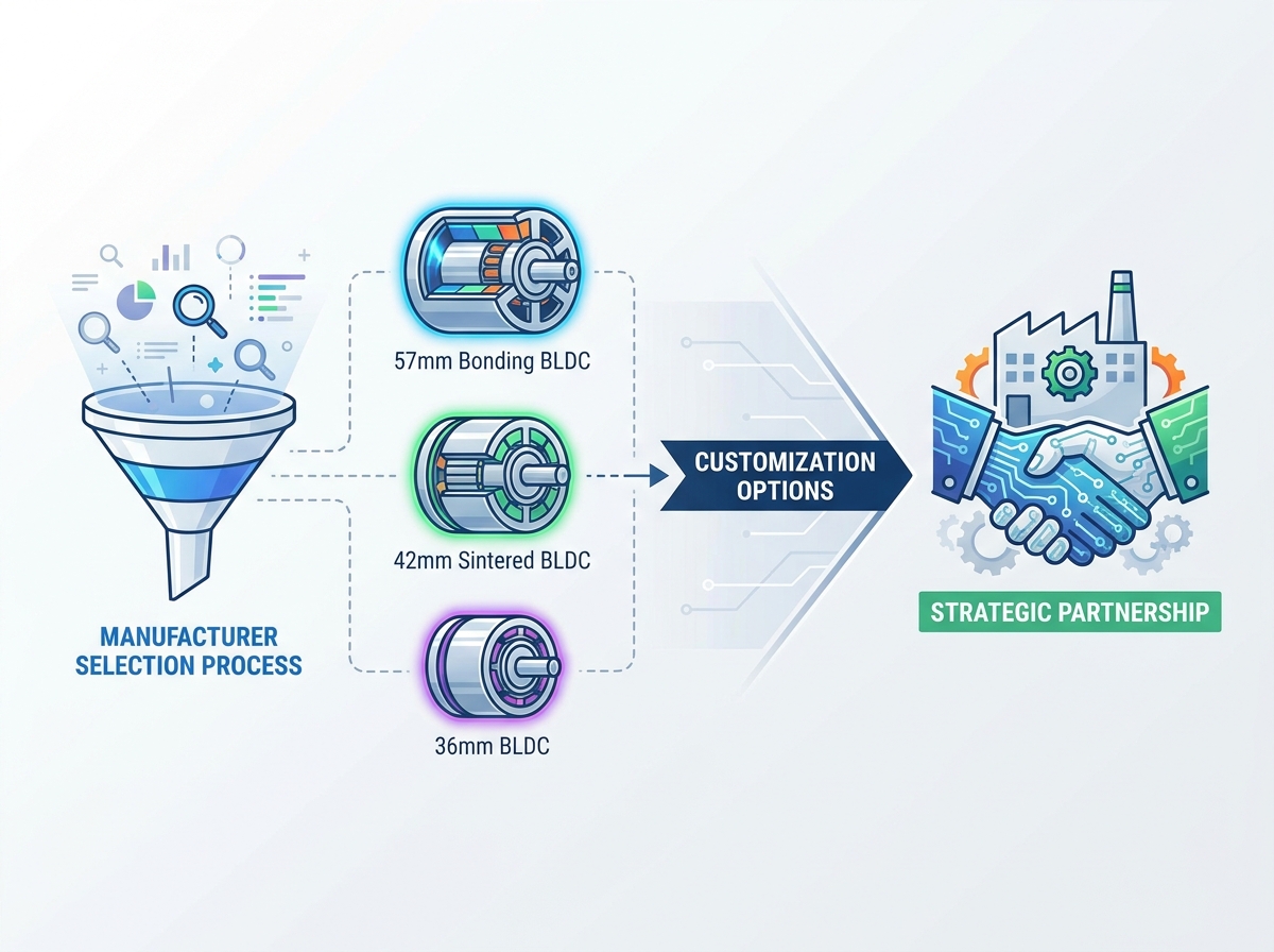
For highly compact applications, such as handheld surgical tools or precision gimbals, a 36mm BLDC motor provides a dense power footprint. Evaluating a vendor for this size requires verifying their micro-machining tolerances and ability to handle fine-gauge magnet wire. The assembly of such small motors requires specialized fixtures to prevent damage to the fragile components during pressing and gluing operations.
Mid-size requirements demand a nuanced approach to magnet selection. When the application requires high magnetic density, rapid acceleration, and maximum peak torque, specifying a 42mm sintered BLDC motor is optimal. Sintered neodymium magnets deliver superior flux density. Conversely, for applications prioritizing cost-effective production and complex multipole magnetization patterns in less demanding torque environments, a 57mm bonding BLDC motor serves as the practical choice. Bonded magnets allow for tighter dimensional tolerances without extensive post-machining.
Motor Type | Primary Advantage | Ideal Application Profile | Magnet Characteristics |
|---|---|---|---|
36mm BLDC | Ultra-compact footprint | Handheld devices, precision optics | High-precision micro-assemblies |
42mm Sintered BLDC | Maximum peak torque and acceleration | Industrial robotics, high-load actuators | High flux density, rigid structure |
57mm Bonding BLDC | Cost-efficiency and complex magnetization | HVAC blowers, consumer appliances | Isotropic properties, tight tolerances |
Generic torque-speed curves are insufficient for custom hardware. The manufacturer must design for specific duty cycles. Continuous duty applications require robust thermal dissipation paths, while intermittent duty cycles allow for higher peak currents and aggressive overdriving. Verify the vendor's ability to model start-stop dynamics and map exact speed-torque curves under transient loads, ensuring the motor does not stall or overheat during sudden mechanical resistance.
Consider an actuator used in a robotic arm. It experiences rapid acceleration, holds a position against gravity, and then decelerates quickly. This dynamic load profile generates significant heat spikes in the windings. The manufacturer must profile the motor's thermal time constant to ensure the peak temperatures during these transient events do not exceed the insulation class ratings. Ask for thermal simulation reports alongside the standard torque-speed curves.
Heat destroys rare-earth magnets and degrades winding insulation. Assess the manufacturer's material science expertise. They must select appropriate insulation classes (e.g., Class F or Class H) based on the target operating environment. High-temperature applications require specific grades of neodymium magnets (such as UH or EH grades) to prevent irreversible demagnetization. Furthermore, the housing design must incorporate effective heat-dissipating features, such as extruded cooling fins or thermally conductive potting compounds, to guarantee durable performance.
Potting compounds offer excellent thermal management for enclosed motors. By filling the air gaps between the stator windings and the motor housing with a thermally conductive epoxy, you create a direct path for heat to escape. This technique significantly lowers the internal winding temperature, allowing the motor to run harder without failing. However, potting adds weight and complicates the manufacturing process. Discuss these trade-offs with your vendor to determine if potting is necessary for your specific application.
Prototyping is useless if the design cannot scale. The vendor must conduct a rigorous DFM review of initial CAD files and specifications. This review identifies potential scaling issues, such as axis misalignments during automated assembly or inadequate stator-rotor clearances that could cause rubbing at high RPMs. By addressing these tolerances early, the manufacturer prevents yield drop-offs and assembly line bottlenecks during mass production.
A thorough DFM review should cover bearing selection and preloading. Improper bearing preload leads to premature failure and excessive acoustic noise. The vendor must analyze the axial and radial loads your application applies to the motor shaft and select bearings with the appropriate dynamic load ratings. They must also design the housing and shaft tolerances to ensure the bearings are seated correctly and preloaded to the optimal specification.
Engineers frequently need to source replacement assemblies or upgrade legacy systems where original documentation or CAD files are missing. Assess the manufacturer’s reverse engineering capabilities. A proficient vendor can take an existing motor, bench-test its performance parameters, tear it down to analyze the winding configuration and lamination geometry, and reconstruct a modernized, manufacturable equivalent.
The reverse engineering process requires specialized equipment. The vendor needs a dynamometer to map the original motor's torque-speed curve accurately. They need precision measurement tools, such as Coordinate Measuring Machines (CMM), to capture the exact dimensions of the housing and shaft. They also need material analyzers to determine the specific grade of magnets and lamination steel used in the original design. Verify that the vendor possesses this equipment in-house.
Customization requires specific tooling, which dictates the prototyping timeline. Establish realistic expectations for lead times. Custom shaft machining, specialized winding jigs, and injection molds for custom connectors typically require several weeks to fabricate. The delivery of the First-Article Inspection (FAI) sample is a critical milestone. Ensure the vendor provides a transparent schedule detailing tooling fabrication, initial assembly, and internal validation before shipping the FAI unit.
Tooling modifications often cause the most significant delays during prototyping. If the initial FAI sample fails to meet the performance specifications, the vendor might need to modify the stamping dies or winding jigs. Ask the vendor about their in-house tooling capabilities. Vendors with in-house machine shops can modify tooling much faster than those who outsource tooling fabrication to third-party suppliers.
The first prototype rarely meets all field requirements perfectly. Assess how the manufacturer handles specification revisions. If initial dynamometer testing reveals that the Kv rating (RPM per volt) is slightly off, the vendor must be agile enough to adjust the winding turns or wire gauge quickly. Fast iteration cycles during the prototyping phase prevent months of schedule slip.
Communication is critical during the iteration phase. You need direct access to the vendor's engineering team, not just a sales representative. Weekly technical review meetings help keep the project on track. The vendor should provide detailed test reports for each prototype iteration, clearly showing the performance changes resulting from the design modifications. This data-driven approach ensures that each iteration moves closer to the final specification.
Baseline facility certifications act as the first filter for vendor selection. ISO 9001 certification is mandatory, demonstrating a formalized quality management system. Depending on the application sector, industry-specific standards are required. Automotive applications demand IATF 16949 compliance, ensuring rigorous defect prevention and supply chain variation control. Medical device integration requires ISO 13485 certification, mandating strict traceability and risk management protocols.
Do not just ask for a copy of the certificate. Ask to see the vendor's quality manual and recent audit reports. A certificate on the wall means nothing if the operators on the floor do not follow the documented procedures. During a facility audit, observe how the vendor handles non-conforming materials. A robust quarantine and corrective action process indicates a mature quality culture.
Consistent production quality relies on comprehensive End-of-Line testing. The vendor must possess automated testing capabilities for every unit rolling off the line. Mandatory protocols include back-EMF measurement to verify magnetic strength and winding consistency, hipot testing to ensure dielectric insulation integrity, and vibration analysis to detect bearing defects or rotor imbalance. Noise and dB level audits are critical for consumer-facing products, while automated dynamometer testing verifies the motor hits the required performance parameters under load.
Back-EMF Measurement: Verifies magnet strength and winding turns.
Hipot Testing: Checks for insulation breakdown between windings and the stator core.
Vibration Analysis: Detects rotor imbalance and bearing defects.
Acoustic Noise Testing: Ensures the motor operates within specified decibel limits.
Automated Dynamometer Testing: Confirms torque and speed performance under load.
Motors must survive their intended operating environments. Assess how the vendor validates life expectancy. This includes accelerated life testing under maximum load. Ingress protection (IP) ratings must be verified through standardized dust and water exposure chambers. Corrosion resistance requires salt spray testing, particularly for marine or outdoor applications. Thermal shock performance testing ensures the motor materials expand and contract without structural failure when exposed to rapid temperature fluctuations.
Accelerated life testing (ALT) helps predict the motor's failure modes and overall lifespan. The vendor should run the motors at elevated temperatures and higher-than-normal loads to accelerate the wear on the bearings and insulation. They should provide a detailed ALT report showing the Weibull distribution of failures. This data allows you to confidently state the expected lifespan of your product to your customers.
Accountability requires strict documentation. The manufacturer must implement batch tracking down to the component level. Raw material certificates are essential, particularly for rare-earth magnet sourcing, to verify material grade and ethical supply chains. Comprehensive inspection reports must accompany every shipment, providing the OEM with data-backed assurance that the lot conforms to the agreed-upon specifications.
Traceability becomes critical during a field failure investigation. If a motor fails in the field, you need to trace it back to the specific production batch. You need to know which batch of magnets was used, which operator wound the stator, and what the EOL test results were for that specific serial number. A vendor with a robust Manufacturing Execution System (MES) can provide this data instantly, helping you identify the root cause and contain the issue quickly.
Geographic location impacts supply chain resilience and communication. Domestic manufacturing offers shorter supply chains, eliminating weeks of ocean freight transit. Communication is streamlined, and adherence to strict regulatory compliance, such as ITAR or Buy American provisions, is guaranteed. Offshore production generally provides higher volume capacity and access to localized raw material hubs, particularly for rare-earth magnets. Engineering teams must weigh logistical friction and communication barriers against production volume requirements.
Consider the impact of time zones on the development cycle. Working with an offshore vendor often means a 12-hour time difference. If you find an issue during testing, you send an email and wait until the next day for a response. This communication lag can add weeks to the prototyping phase. Domestic vendors allow for real-time collaboration, rapid troubleshooting, and easier facility visits. You must decide if the lower unit cost of offshore manufacturing justifies the slower development cycle.
Transitioning from prototype to production requires flexible scaling. Discuss pilot run negotiations with potential vendors. A manufacturer demanding massive MOQs immediately after prototyping introduces severe inventory risk. Evaluate their capacity to scale smoothly. The ideal partner can execute a pilot run of a few hundred units for beta testing, and then seamlessly ramp up to tens of thousands of units using automated winding and assembly lines without suffering quality degradation.
Ask the vendor about their capacity utilization. If their factory is already running at 95% capacity, they will struggle to accommodate your volume spikes. You want a vendor with room to grow. They should have a clear plan for adding new production lines and hiring additional operators as your volume increases. Discuss their lead times for scaling up production and ensure they align with your sales forecasts.
Custom designs represent valuable intellectual property. Outline the risks of IP theft when sharing proprietary CAD files and performance requirements. Vet the manufacturer's internal data security protocols. Compartmentalized manufacturing—where different components are machined in separate facility zones—adds a layer of security. Furthermore, ensure Non-Disclosure Agreements (NDAs) are legally enforceable within the manufacturer's operating jurisdiction to protect your hardware innovations.
Physical security is just as important as data security. During a facility audit, observe how the vendor controls access to the production floor. Are visitors escorted at all times? Are cameras prohibited? Do they have secure areas for assembling highly confidential projects? A vendor that takes physical security seriously is more likely to protect your intellectual property.
Selecting a custom motor manufacturer dictates the mechanical reliability and market success of the final hardware. The cheapest per-unit quote often masks poor DFM practices, the use of subpar materials, or a complete lack of rigorous EOL testing. Prioritize engineering alignment and quality infrastructure over initial unit cost estimates.
To narrow down a list of potential vendors, utilize a strict shortlisting logic. Weight their in-house engineering support, verify their quality certifications, and assess their realistic tooling lead times. This methodology effectively filters out basic assembly houses, leaving only capable manufacturing partners.
Compile a detailed Request for Quote (RFQ) including torque-speed curves, dimensional constraints, and environmental conditions.
Request an initial engineering consultation with your top three shortlisted vendors to evaluate their technical responsiveness.
Demand a comprehensive Design for Manufacturing (DFM) review before authorizing any custom tooling fabrication.
Establish clear End-of-Line (EOL) testing protocols and require automated test reports for every production batch.
A: A standard custom prototype typically requires 4 to 8 weeks. This timeline depends heavily on tooling requirements. Machining custom shafts, fabricating specific winding jigs, and sourcing non-standard magnets add to the lead time, whereas modifying an existing stator design can be completed faster.
A: Sintered magnets offer higher magnetic strength, delivering greater peak torque and acceleration. Bonded magnets have lower flux density but allow for complex, multi-pole shapes and tighter manufacturing tolerances without expensive post-machining, making them highly cost-effective for specific applications.
A: Yes, capable manufacturers can reverse-engineer existing motors. The process involves dimensional laser scanning, stator lamination analysis, and winding profiling. They bench-test the original unit to map its performance, then create new CAD models to manufacture a modernized equivalent.
A: Continuous duty cycles require robust thermal dissipation strategies, lower slot fill factors to manage heat, and high-grade insulation classes. Intermittent duty cycles allow engineers to design for higher peak currents and aggressive torque output, as the motor has time to cool between operations.
A: MOQs are dictated by custom tooling amortization, raw material minimums (especially for custom magnet batches), and assembly line setup times. Manufacturers calculate the volume required to make the production run economically viable, which typically ranges from 500 to several thousand units.