close
Choose Your Site
Global
Social Media
Views: 0 Author: Site Editor Publish Time: 2026-09-22 Origin: Site
Achieving high positional accuracy and smooth motion without escalating system complexity remains a persistent engineering challenge in motion control. Engineers constantly seek a balance between performance and budget. Default choices often force a compromise. While 2-phase stepper motors dominate the market due to their ubiquity, they frequently introduce unacceptable resonance, overshoot, and vibration at low speeds. Conversely, 5-phase motors or closed-loop servo systems drastically inflate the Bill of Materials and require complex tuning procedures. The 3 Phase Stepper Motor emerges as the strategic middle ground. It delivers the necessary resolution and acoustic profile for high-precision tasks while maintaining the simplicity of open-loop control. This solution bridges the gap, offering enhanced stability and accuracy without the extreme costs associated with premium alternatives.
Optimal Step Angle: 3-phase stepper motors typically operate at a 1.2° step angle, inherently offering 50% higher baseline resolution than standard 1.8° 2-phase motors before microstepping is applied.
Resonance Mitigation: The 3-phase magnetic circuit naturally cancels out third-harmonic resonance, making it an inherently stable stepper motor at critical low-to-medium speed ranges.
Cost-to-Performance Ratio: Bridges the gap between 2-phase and 5-phase technologies, providing near 5-phase smoothness at a price point closer to premium 2-phase systems.
Drive Dependency: Requires specific 3-phase drives; retrofitting existing 2-phase systems requires a complete drive-and-motor swap, necessitating careful BOM planning.
Standard 2-phase motors suffer from inherent physics limitations. Torque ripple, overshoot, and mid-band resonance plague these designs. These issues become highly problematic in precision applications. When a 2-phase motor operates at low speeds, the discrete steps cause the rotor to oscillate around its target position. This oscillation generates mechanical vibration. Mid-band resonance typically occurs between 100 and 200 steps per second. If the motor operates continuously in this frequency band, it loses synchronization with the drive pulses. This results in a complete stall and lost steps.
Despite these flaws, 2-phase motors remain the common default. Low initial costs and wide availability drive this adoption. However, engineers must migrate to a more advanced phase configuration when performance thresholds demand tighter tolerances. You cannot fix inherent mechanical resonance with software alone. Electronic dampening helps, but it often reduces available torque.
Vibration directly leads to surface finish defects in machining operations. In CNC milling, this manifests as chatter marks or "salmon skin" on the final part. In optical inspection equipment, vibration causes blurring. Cameras capture distorted images, rendering measurements inaccurate. Pushing 2-phase motors to higher speeds under load significantly increases the risk of missed steps. The high inductance of 2-phase windings prevents current from building up fast enough at high RPMs, causing a sharp drop in torque.
Specifying 5-phase motors introduces substantial supply chain complications. The supplier base is limited. Component costs are significantly higher, despite their superior low-vibration characteristics. You lock your design into a niche ecosystem. If a 5-phase drive fails in the field, sourcing a replacement quickly becomes a logistical nightmare. This makes them difficult to justify for many standard industrial projects.
Servo motors present entirely different challenges. They require complex tuning, high-resolution encoders, and sophisticated PID controllers. Servos operate in a closed loop. They constantly read encoder feedback and adjust current to maintain position. When absolute standstill stability is required, servos often suffer from hunting or dithering. The controller constantly overcorrects by one or two encoder counts. This micro-movement is unacceptable in applications like laser targeting or semiconductor wafer probing. Stepper motors, by contrast, lock into position magnetically and hold perfectly still.
The internal stator and rotor tooth alignment dictates motor performance. A 3-phase design typically features three stator phases driving a hybrid rotor. The stator has a specific number of poles, usually divisible by three, wrapped with copper windings. The rotor contains a permanent magnet with toothed steel caps. This specific geometry optimizes magnetic interaction.
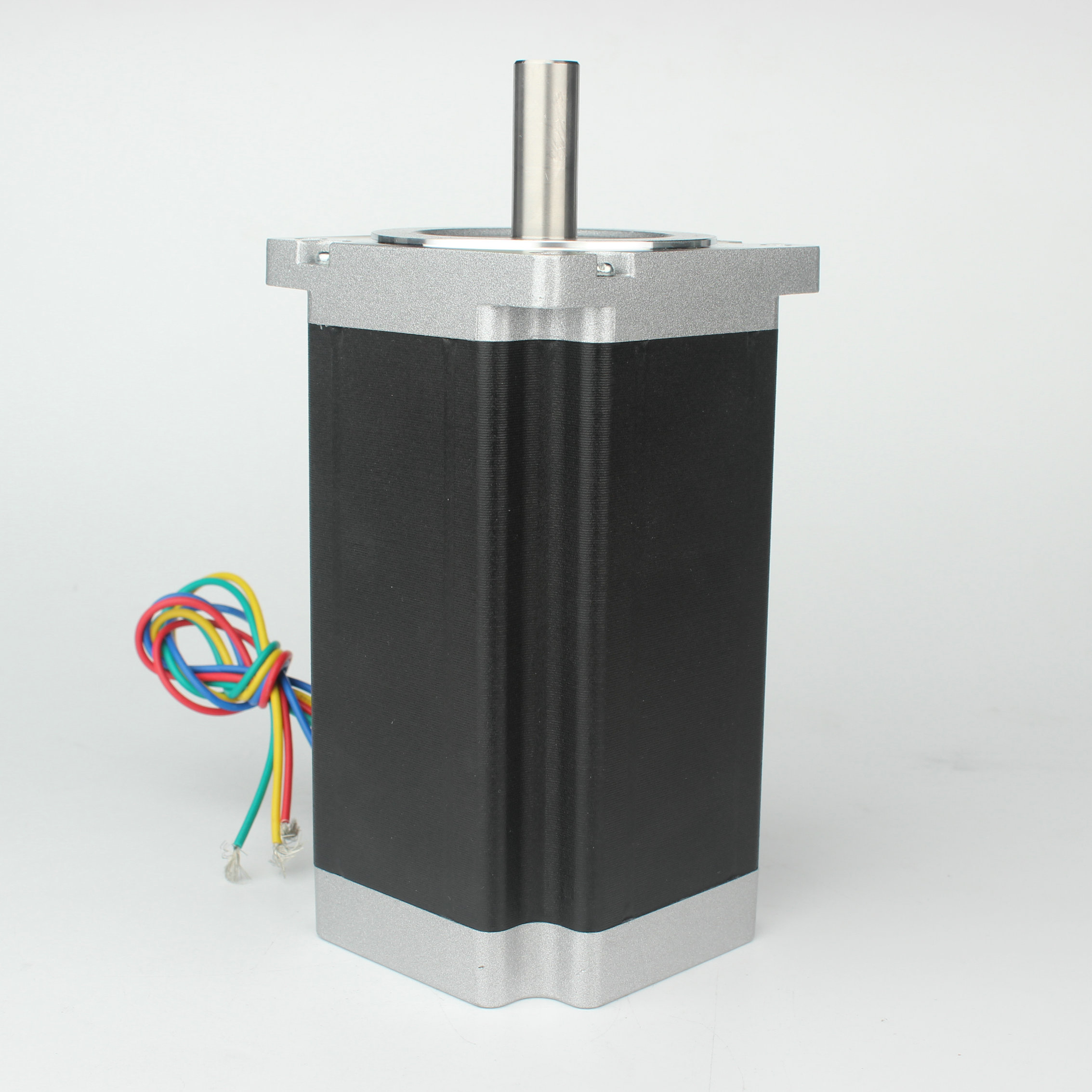
The overlapping magnetic flux in a 3 Phase Stepper Motor provides a more continuous, balanced torque delivery compared to standard 2-phase designs. In a 2-phase motor, the torque drops significantly between steps. In a 3-phase motor, the three phases overlap. As one phase loses magnetic grip, the next phase is already pulling the rotor. This overlap smooths out the torque ripple. The result is a fluid rotation that mimics the behavior of a much more expensive servo motor.
A 3-phase motor features a 1.2° step angle. This yields exactly 300 full steps per revolution. This contrasts sharply with the 1.8° (200 steps/rev) of a 2-phase and the 0.72° (500 steps/rev) of a 5-phase motor. The 1.2° angle provides a 50% increase in mechanical resolution over the standard 2-phase baseline.
Different drive modes impact performance differently. Full-step mode energizes one or two phases at a time, providing maximum torque but the highest vibration. Half-step mode doubles the resolution to 600 steps per revolution. Microstepping divides the current into sine waves, creating thousands of micro-positions between the physical poles.
The baseline 1.2° geometry reduces reliance on extreme microstepping ratios to achieve fluid, continuous motion. High microstepping ratios (like 1/256) in 2-phase motors often fail to deliver accurate positioning under load. The magnetic stiffness is too low. A 3-phase motor achieves smooth motion at lower microstepping ratios (like 1/8 or 1/16). This inherent design advantage helps maintain higher holding torque while ensuring smooth operation.
Motor Type | Step Angle | Steps per Revolution | Resonance Risk | System Complexity |
|---|---|---|---|---|
2-Phase Stepper | 1.8° | 200 | High | Low |
3-Phase Stepper | 1.2° | 300 | Low | Medium |
5-Phase Stepper | 0.72° | 500 | Very Low | High |
The cancellation of third-harmonic torque in 3-phase systems drastically reduces mechanical oscillation. Torque harmonics are unwanted variations in the magnetic pull. The 3-phase winding configuration naturally cancels out the third harmonic, which is the primary cause of low-speed vibration in stepper motors. This design inherently minimizes settling times during step transitions.
When a motor steps, the rotor overshoots the target position slightly and rings back and forth before settling. This is called transient ringing. The 3-phase design dampens this ringing mechanically. Reduced vibration translates directly to lower acoustic noise and zero-settling-time advantages in the field. This establishes a true low vibration stepper motor profile. Equipment runs quieter, and cycle times decrease because the controller does not have to wait for the mechanics to settle before taking a measurement.
Analyzing the torque-speed curve reveals significant advantages. 3-phase motors maintain usable torque at higher RPMs better than 2-phase equivalents. This is due to lower back-Electromotive Force (back-EMF) and lower inductance per phase. Inductance resists changes in current. At high speeds, the drive has very little time to push current into the windings before the next step pulse arrives.
Lower inductance allows the current to reach its target value faster. The 3-phase design prevents the sudden torque drop-offs common in 2-phase setups. You can run a 3-phase motor at higher velocities without stalling. This ensures consistent high-speed performance for rapid traverse movements in automated machinery.
Standard mechanical step accuracy typically ranges from ±3% to ±5% of a step. This mechanical error is non-cumulative from step to step. If the motor moves one step or one million steps, the final position error remains within that ±5% window of a single step. This makes the motor highly reliable for repetitive, high-cycle precision tasks.
A smaller base step angle translates to a smaller absolute positional error band in arcminutes. Five percent of 1.2° is significantly smaller than five percent of 1.8°. When driving a ball screw or a rack and pinion, this tighter angular tolerance translates directly to tighter linear accuracy on the machine bed.
While 2-phase drives offer high microstep fractions, actual mechanical positioning accuracy degrades under load. The magnetic restoring force between microsteps is weak. If external friction or load inertia pushes against the rotor, it will deflect from the intended microstep position. A 3-phase system holds microstep positions more rigidly due to the overlapping magnetic fields.
Microstepping alleviates overshoot and noise issues. However, the 3-phase motor requires less electronic dampening to achieve a stable stepper motor state. You do not need to rely on complex drive algorithms to smooth out the motion. The motor mechanics do the heavy lifting. This simplifies drive configuration and reduces the risk of tuning errors.
The supply chain reality dictates that 2-phase is ubiquitous. You can find a 2-phase motor and drive anywhere. 5-phase remains highly proprietary and niche. Often, you must buy the motor and drive from the exact same manufacturer. The 3-phase option is rapidly growing as a global standard for a precision industrial stepper motor. Multiple manufacturers now produce compatible 3-phase motors and drives, offering better availability and competitive sourcing compared to 5-phase systems.
These applications demand zero-vibration standstill and highly precise position control. Wafer inspection stages must move rapidly to a coordinate and stop instantly. Rapid point-to-point moves without settling delays are critical for throughput. Any vibration during the inspection flash ruins the image. The 3-phase motor provides the necessary stiffness and acoustic profile to meet these stringent requirements.
Smoother torque delivery and reduced torque ripple eliminate chatter marks on finished parts. In 3D printing, 2-phase motors often leave vertical artifacts on the printed walls, known as VFA (Vertical Fine Artifacts). Upgrading to a 3-phase system eliminates these artifacts. This ensures superior surface quality in advanced manufacturing processes without upgrading to expensive servo systems.
The acoustic benefits are essential in quiet laboratory environments. Automated pipetting systems require precise volumetric control. This relies heavily on stable, repeatable motion. A sudden jerk from a resonating 2-phase motor can cause liquid to splash, contaminating the sample. The smooth acceleration profile of a 3-phase motor prevents this issue entirely.
A strict requirement exists for compatible 3-phase stepper drives. You cannot wire a 3-phase motor into a 2-phase drive. Phase-mismatch or attempting to use generic 2-phase drives will result in system failure. The drive must have three distinct output bridges (U, V, W) to sequence the currents correctly. Always ensure drive compatibility before installation. Review the wiring diagrams carefully.
Setting the correct current limits and microstepping resolutions is vital. You must avoid resonance bands specific to the application's load inertia. Proper tuning guarantees optimal performance and longevity. Start with a lower microstepping resolution, such as 1000 pulses per revolution. Test the motion profile. If you detect resonance at a specific speed, adjust the acceleration ramp or change the microstepping value to shift the resonance frequency away from your operating speed.
Wiring configurations must be executed correctly. 3-phase motors typically use a Star (Y) or Delta configuration internally. Most modern 3-phase steppers bring three or six wires out to the terminal. Ensure you connect U, V, and W to the corresponding drive terminals. Implement adequate heat dissipation strategies for continuous duty cycles. Mount the motor to a thermally conductive aluminum bracket. This acts as a heatsink and prevents thermal degradation of the internal winding insulation.
Verify the motor phase resistance matches the drive specifications.
Connect the U, V, and W phases securely to the drive terminals.
Ensure the drive is grounded to the machine chassis to prevent electrical noise.
Set the drive current to match the motor's rated RMS current, not the peak current.
Run a slow-speed test profile to verify smooth rotation before attaching the mechanical load.
Audit your current motion control system to identify specific zones where mid-band resonance or lost steps occur.
Procure a compatible 3-phase motor and drive evaluation kit to perform empirical load-inertia testing on your test bench.
Update your Bill of Materials to reflect the new drive requirements, ensuring you remove any legacy mechanical dampeners.
Configure the microstepping resolution on the new drive to match your application's specific positional accuracy requirements.
A: The primary difference lies in the stator windings and step angle. A 3-phase motor uses three winding circuits and typically offers a 1.2° step angle, compared to the 1.8° angle of a 2-phase motor. This geometry reduces torque ripple and mechanical vibration, providing smoother operation at low speeds.
A: No. They are electrically incompatible due to different phase winding configurations. You must use a dedicated 3-phase drive equipped with U, V, and W outputs to sequence the currents correctly across the three motor phases.
A: The 3-phase design typically features lower phase inductance. This allows current to build up faster in the windings, overcoming back-EMF more effectively. Consequently, the motor maintains higher torque at elevated RPMs compared to standard 2-phase motors.
A: It operates inherently in open-loop like other steppers, requiring no encoder for basic positioning. However, an encoder can be added to the rear shaft for stall detection or closed-loop control if the specific application demands absolute position verification.
A: It reduces vibration through the natural cancellation of the third harmonic in the torque profile. Combined with the smaller 1.2° step angle, these factors minimize overshoot and transient resonance, resulting in significantly quieter and smoother motion.