close
Choose Your Site
Global
Social Media
Views: 0 Author: Site Editor Publish Time: 2026-09-21 Origin: Site
In precision automation, achieving exact positioning without the prohibitive cost and complexity of servo systems remains a primary engineering challenge. Selecting the wrong motor leads to two costly extremes. Over-speccing wastes capital and increases the machine footprint. Under-speccing results in missed steps, resonance-induced downtime, and stalled production lines. You need a reliable method to match motor capabilities with mechanical demands.
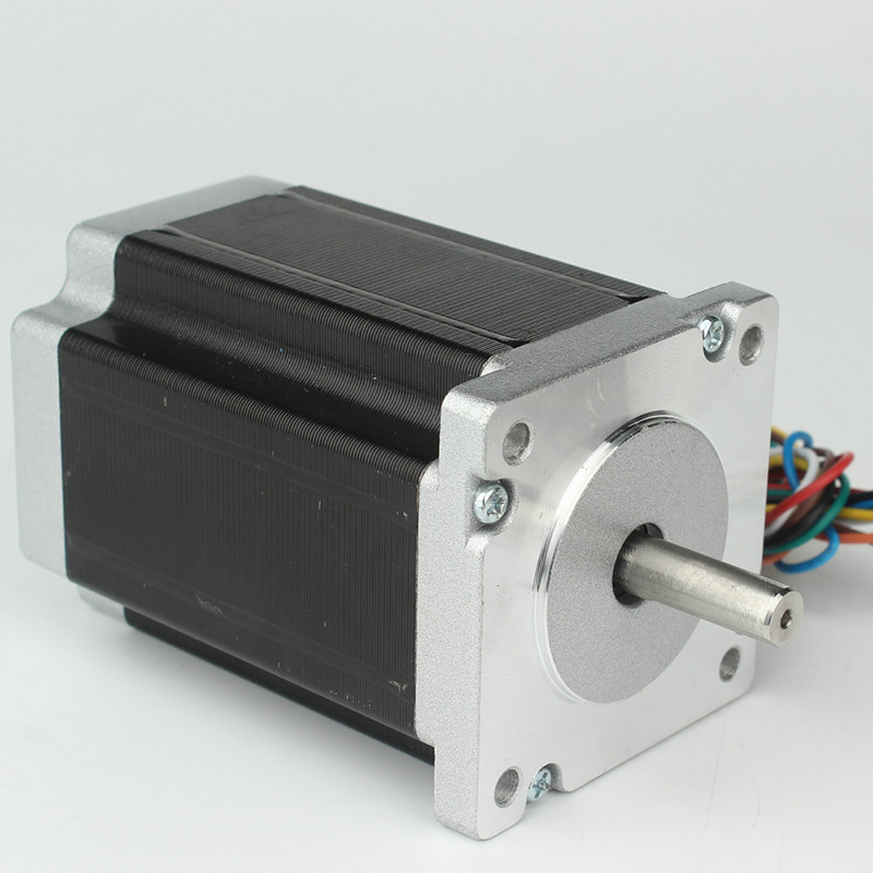
Moving from a conceptual design to a reliable physical system requires a strict evaluation framework. You must analyze load dynamics, control ecosystems, and long-term durability requirements. This guide breaks down how to size, configure, and select a DC Stepper Motor for your specific application. You will learn to navigate torque curves, inertia matching, and driver compatibility to ensure optimal performance across various industrial environments.
Prioritize the Torque Curve Over Holding Torque: A motor’s holding torque is a static metric; dynamic applications require evaluating the pull-out torque curve at your target operating speed.
Inertia Matching is Critical: For stable operation and to prevent missed steps, the load-to-rotor inertia ratio should ideally be kept between 1:1 and 10:1.
Microstepping Reduces Usable Torque: While microstepping increases resolution and reduces resonance, it exponentially decreases incremental holding torque—a critical trade-off in heavy automation.
Ecosystem Compatibility Dictates Success: The physical motor is only half the solution; seamless integration with PLCs, drivers, and power supplies determines the system's actual reliability.
First, identify the mechanical system converting motor rotation into physical work. Common mechanisms include ball screws, lead screws, timing belts, pulleys, rack and pinion setups, and direct drives. Each system presents unique physical demands. You must analyze how friction, efficiency losses, and mechanical play affect the workload. Backlash in a gear system requires different compensation than belt stretch in a linear actuator. For instance, a ball screw offers high efficiency and rigidity but introduces significant reflected inertia back to the motor shaft. Conversely, a timing belt system provides lower inertia but introduces compliance and potential resonance issues that must be managed through driver tuning.
When evaluating these mechanisms, document the exact mass of the load, the friction coefficient of the linear guides, and the efficiency rating of the drive components. A direct drive rotary table will have a near 100% efficiency but a massive inertia mismatch if not sized correctly. A lead screw might only offer 40% efficiency, meaning more than half your motor's torque is lost to friction before moving the actual payload. Understanding these mechanical realities is the foundational step in motor sizing.
Map out the velocity profile over time. You need to define acceleration, constant speed, deceleration, and dwell times accurately. Differentiate between the peak torque required during rapid acceleration and the running torque needed during constant speed phases. When sizing an automation line motor, understanding this dynamic profile prevents unexpected stalls during aggressive moves. A trapezoidal move profile is standard, where the motor accelerates linearly to a target velocity, holds that velocity, and then decelerates linearly.
For more demanding applications, an S-curve profile might be necessary to reduce jerk and mechanical wear, though this requires higher peak torque during the middle of the acceleration phase. Calculate the root mean square (RMS) torque if the application involves continuous, repetitive moves with short dwell times. This helps in estimating the thermal load on the motor. If the motor spends 80% of its cycle accelerating and decelerating heavy loads, the thermal demands will be vastly different than a motor that accelerates once and runs at a constant velocity for hours.
Break down the standard step angles. Most industrial applications use either 1.8-degree (200 steps per revolution) or 0.9-degree (400 steps per revolution) motors. Map the native resolution to your chosen mechanical drive system. This determines your final linear resolution. For example, calculate the exact travel per step in microns for a ball screw to ensure it meets your positioning tolerance. If you have a ball screw with a 5mm pitch and a 1.8-degree motor, one full step equals 0.025mm of linear travel.
Do not rely on microstepping to achieve mechanical accuracy. Microstepping is primarily for smoothness and resonance reduction. Due to friction and magnetic non-linearities, a motor commanded to move one 1/16th microstep may not physically move until several microsteps have accumulated enough torque to overcome static friction. Always design your mechanical transmission so that the native full-step or half-step resolution meets your accuracy requirements.
Relying solely on holding torque leads to system failure. Holding torque only applies when the motor is stationary. You must read a speed-torque curve provided by manufacturers. This identifies the actual pull-out torque available at your operating RPMs. Always define a safety margin. Typically, you need 30% to 50% extra torque above the calculated requirement to account for friction and mechanical wear over time. As a motor spins faster, its inductance prevents current from rising fast enough to reach the rated level before the next step occurs, causing torque to drop off steeply.
When reviewing a speed-torque curve, ensure the manufacturer's test conditions match your intended setup. A curve generated with a 48V power supply will look vastly different than one generated with a 24V supply. If your application requires 2 Nm of torque at 1000 RPM, and the curve shows exactly 2 Nm at that speed, you must select a larger motor. Operating right on the edge of the pull-out torque curve guarantees missed steps the moment a bearing gets slightly sticky or the load increases marginally.
Bipolar motors feature a two-phase winding structure. Current flows in both directions through the entire winding. The primary advantage is higher torque output for a given physical size. This happens due to the full utilization of the copper windings. They require an H-bridge driver to reverse the current flow. While this adds slight complexity to the circuit, H-bridge drivers are standard in modern automation systems. The wiring typically consists of four leads, making connection straightforward. Because all the copper in the stator is actively generating a magnetic field at any given time, bipolar motors offer the best power density.
In heavy industrial settings, bipolar parallel and bipolar series wiring options exist for 8-lead motors. Bipolar parallel wiring lowers the phase inductance, allowing for better high-speed torque performance, though it requires a driver capable of supplying higher current. Bipolar series wiring increases inductance, providing excellent low-speed torque but causing torque to drop off rapidly as speed increases. Choosing between these wiring methods allows engineers to tailor the motor's performance curve to the specific application.
Unipolar motors use a four-phase winding structure with a center tap. This design allows current to flow in only one direction per half-winding. The main advantage is simpler control circuitry. You do not need to reverse the current. However, there is a major trade-off. They produce approximately 30% less torque than a bipolar motor of the exact same size. This makes them less common in heavy industrial applications. They typically feature five, six, or eight leads.
While unipolar motors were popular decades ago when complex driver electronics were expensive, the advent of cheap, reliable bipolar chopper drivers has rendered them largely obsolete for new industrial designs. They are still found in legacy equipment and very low-cost consumer devices where minimizing the component count on the control board is the absolute highest priority. For any serious automation project, bipolar configurations are the standard.
Feature | Bipolar Stepper Motor | Unipolar Stepper Motor |
|---|---|---|
Winding Structure | Two-phase | Four-phase with center tap |
Torque Output | High (Full winding utilization) | Lower (~30% less than bipolar) |
Driver Complexity | Requires H-bridge | Simpler circuitry |
High-Speed Performance | Excellent (with parallel wiring) | Poor due to high inductance |
Industrial Use | Highly common | Less common |
Low weight and compact size define NEMA 17 applications. Engineers prioritize these traits for desktop equipment and prototyping. It stands as the ubiquitous 3D printer stepper motor and powers light-duty pick-and-place machines. Leading manufacturing benchmarks allow for dynamic evaluation using standardized testing. You can easily source these components for rapid iteration and proof-of-concept builds. They typically offer holding torques ranging from 0.2 to 0.6 Nm.
Despite their small size, NEMA 17 motors can achieve impressive speeds if paired with a sufficiently high voltage power supply and a low-inductance winding. However, their small shaft diameter (typically 5mm) limits the amount of radial load they can handle. Direct driving heavy belts or large pulleys can lead to premature bearing failure or shaft deflection. Always ensure the mechanical load is properly supported by external bearings rather than relying solely on the motor's internal bearings.
High-torque requirements demand larger form factors. Transitioning to an industrial DC stepper motor unlocks capabilities for CNC routing and heavy conveyor indexing. These motors bring physical implications. Expect larger shaft diameters, increased rotor inertia, and the absolute necessity for higher voltage power supplies. Evaluate leading industrial hardware providers known for extreme durability and reliable integration in harsh environments. NEMA 23 motors typically range from 1 to 3 Nm, while NEMA 34 motors can exceed 12 Nm of holding torque.
When moving to NEMA 34 and larger sizes, the rotor inertia becomes a significant factor in the system's dynamics. These massive rotors require substantial energy just to accelerate themselves, before even considering the attached load. This makes inertia matching even more critical. Furthermore, the high currents required (often 6 to 8 amps per phase) necessitate robust wiring, heavy-duty connectors, and industrial-grade drivers with active cooling to prevent thermal shutdown during continuous operation.
NEMA Frame Size | Typical Faceplate Dimensions | Common Holding Torque Range | Primary Applications |
|---|---|---|---|
NEMA 14 | 35 x 35 mm | 0.1 - 0.3 Nm | Small robotics, optical instruments |
NEMA 17 | 42 x 42 mm | 0.2 - 0.6 Nm | 3D printers, light automation |
NEMA 23 | 57 x 57 mm | 1.0 - 3.0 Nm | CNC routers, packaging machines |
NEMA 34 | 86 x 86 mm | 4.0 - 12.0 Nm | Heavy material handling, large mills |
You must calculate the inertia of your specific drive mechanism. Ball screws, rack and pinion gears, and belt drives all behave differently under acceleration. Follow the 10:1 load-to-rotor inertia rule. Keeping the load inertia within ten times the rotor inertia maintains control during rapid acceleration and deceleration. Exceeding this ratio often causes the motor to lose synchronization and miss steps. For highly dynamic applications requiring rapid point-to-point moves, aim for a ratio closer to 3:1 or 5:1.
Friction must also be quantified. Static friction (stiction) is the force required to initiate movement, while kinetic friction is the force required to maintain movement. Stiction is always higher. Your motor must have enough torque at zero speed to overcome stiction and accelerate the load simultaneously. Use a torque wrench on your mechanical assembly to measure the breakaway torque physically. Add this measured value to your theoretical acceleration torque calculations to ensure your motor sizing is grounded in reality.
Microstepping drivers divide standard steps into smaller increments to reduce vibration. This creates smoother motion at low speeds. However, you face a mathematical reality regarding torque. A half-step yields roughly 70% incremental torque. A 1/16 step yields less than 10% incremental torque. You must balance the desire for smooth operation with the severe risk of stalling under a heavy load. If you command a 1/16th microstep, the motor only generates about 9.8% of its holding torque to move to that new position.
If the load friction exceeds this small amount of torque, the motor shaft will not move. The driver will continue to increment the microsteps, building up current in the windings until enough torque is generated to overcome the friction, resulting in a sudden jump rather than smooth motion. For heavy industrial loads, stick to half-stepping or quarter-stepping. Reserve high microstepping resolutions (like 1/64 or 1/128) for applications with near-zero friction and low inertia, such as optical positioning stages.
Voltage, winding inductance, and high-speed torque share a direct relationship. Your voltage must be high enough to overcome inductive reactance rapidly. Apply a general rule of thumb. Size the power supply voltage to be 4 to 25 times the motor's rated voltage, staying within the driver's maximum limit. Size the power supply current based on actual peak driver demand, not just the motor’s rated phase current. A 3mH inductance motor running at 48V will maintain its torque to a much higher RPM than the same motor running at 24V.
Do not undersize the power supply current. While chopper drivers regulate the current down to the motor, during rapid acceleration, the driver will pull significant transient currents from the supply. If the power supply cannot handle these spikes, the voltage will drop, the driver may fault out, or the motor will stall. Use unregulated linear power supplies or high-quality switching supplies designed specifically for inductive motor loads, which can handle regenerative voltage spikes during rapid deceleration.
Evaluate drivers based on ease of coding, available control modes, and physical durability. Contrast your control options carefully. Simple Step/Direction pulses work well for standalone axes. Integrated fieldbus networks like Modbus, EtherCAT, CANopen, or EtherNet/IP provide advanced PLC integration. Networked drivers offer real-time diagnostics and simplify wiring across large automated production lines. Instead of running individual pulse and direction wires for every axis back to a central controller, you daisy-chain a single communication cable.
Advanced drivers also offer features like sensorless stall detection, which monitors the back-EMF of the motor to detect when it is losing synchronization. This provides a pseudo-closed-loop capability without the cost of an external encoder. Furthermore, look for drivers with anti-resonance algorithms. These algorithms actively monitor the motor's current and inject small phase shifts to dampen mid-frequency resonance, allowing the motor to run smoothly across its entire speed range.
Compare the open-loop precision of a stepper against standard brushed or brushless DC motors. Steppers excel at exact positioning without external feedback. Conventional DC motors provide continuous, high-speed rotation but lack native positional accuracy. If your application requires spinning a fan or driving a pump at high RPMs, a conventional DC motor is better. If you need to move exactly 45 degrees, use a stepper. Steppers are designed for high torque at low speeds, whereas conventional DC motors are designed for high power at high speeds.
Attempting to use a stepper motor for continuous high-speed rotation is inefficient. The high pole count that gives steppers their precision also creates high iron losses and eddy currents at high speeds, generating excessive heat. Conversely, trying to position a standard DC motor accurately requires a high-resolution encoder, a complex PID control loop, and a servo drive, significantly increasing the system's complexity and cost.
Define the threshold where you must transition to a servo system. Speeds exceeding 2000 RPM, highly dynamic loads, and an absolute requirement for zero position loss demand servos. However, closed-loop steppers offer a strong middle-ground solution. By adding an encoder to a stepper, you gain stall detection and position correction. This serves cost-sensitive industrial applications perfectly. Closed-loop steppers operate like traditional steppers until a position error is detected, at which point the driver increases current to force the motor into the correct position.
Servos excel in applications requiring constant torque across a massive speed range and rapid, unpredictable load changes. They only draw the current necessary to move the load, making them highly energy-efficient. Steppers, even closed-loop ones, generally draw near full current constantly. If your application involves moving a known, consistent load to precise positions at moderate speeds, a stepper is the most robust and cost-effective choice. If you are building a high-speed pick-and-place robot handling variable payloads, a servo is mandatory.
Motors risk losing synchronization at specific speeds due to natural resonance frequencies. This mid-frequency resonance causes severe vibration and stalling. You can implement several mitigation tactics. Install mechanical dampers on the motor shaft. Utilize microstepping to smooth out the energy pulses. Program your controller to accelerate quickly through known resonance bands to avoid prolonged vibration. Resonance typically occurs between 100 and 200 RPM, depending on the motor's inductance and the load inertia.
If you command a motor to run continuously at its exact resonant frequency, the vibration will amplify until the rotor loses synchronization with the stator field, resulting in a loud grinding noise and zero rotation. Modern digital stepper drivers are excellent at mitigating this through electronic damping, but mechanical solutions like elastomeric couplings between the motor and the load also help absorb these destructive vibrations.
Steppers draw maximum current even at a complete standstill to maintain holding torque. This reality generates significant heat. Implement thermal management strategies immediately. Enable idle current reduction settings on your driver to drop current when stationary. Mount the motors to large metal brackets acting as heat sinks. In extreme continuous duty cycles, consider active cooling solutions like forced air. A stepper motor running at its rated current can easily reach surface temperatures of 80°C to 90°C, which is normal but can be hazardous to operators and nearby sensitive components.
If your application requires the motor to hold a load against gravity (like a vertical Z-axis), you cannot reduce the idle current too much, or the load will drop. In these cases, consider adding a mechanical brake to the motor shaft. The brake engages when the motor stops, allowing you to cut power to the motor entirely, eliminating heat generation during long dwell periods.
Industrial environments present a high risk of Electromagnetic Interference (EMI). Unshielded motor cables act as antennas, picking up noise and causing erratic driver behavior. Always use shielded cables for motor phases and encoder feedback. Implement proper grounding techniques. Connect the shield drain wire at the driver end only to prevent ground loops between the motor, driver, and PLC. Route high-voltage motor cables far away from low-voltage logic and communication lines.
Failure to manage EMI results in phantom steps, where the driver interprets electrical noise on the step/direction lines as actual command pulses. This causes the axis to drift over time, ruining positional accuracy. Use twisted-pair wiring for all differential signals and ensure your power supply ground is solidly connected to the machine frame.
Choosing the right motor is an exercise in balancing the pull-out torque curve, inertia matching, and driver compatibility. Do not just buy the highest holding torque available. Follow a strict step-by-step procurement approach. Define the drive mechanism and calculate load inertia. Map the motion profile and operating patterns. Select the physical NEMA size and winding type. Match it with an appropriate driver and communication protocol. Finally, prototype and validate performance using a dynamometer under real load conditions.
Request detailed speed-torque curves from manufacturers before purchasing.
Consult with application engineers to verify complex inertia calculations.
Begin testing driver compatibility with your existing PLC architecture immediately.
Implement thermal management strategies during the initial design phase.
A: A conventional DC motor spins continuously when voltage is applied, lacking native positional control. A stepper motor moves in discrete, exact steps based on electrical pulses, allowing for precise open-loop positioning without external encoders.
A: Calculate the total load torque, including friction, gravity, and acceleration forces. Multiply this base calculation by a safety factor of 1.3 to 1.5. Remember to verify dynamic pull-out torque at your target speed, not just static holding torque.
A: Belt drives typically have lower friction but higher compliance, requiring motors that can handle sudden load shifts. Ball screws offer high efficiency and rigidity but present higher reflected inertia, demanding careful inertia matching.
A: Yes, but heat management is critical. Because they draw full current to maintain torque, continuous operation generates significant heat. You must use proper heat sinks, ventilation, or driver settings that reduce idle current.
A: Losing steps usually results from exceeding the motor's pull-out torque at a given speed. It can also stem from poor inertia matching, insufficient power supply voltage, or hitting a mid-frequency resonance band without proper microstepping or damping.