
close
Choose Your Site
Global
Social Media

Views: 0 Author: Site Editor Publish Time: 2026-06-25 Origin: Site


Selecting the wrong motor type can severely impact an entire mechanical system. You risk premature mechanical failure, excessive thermal loads, or unnecessary controller complexity when components mismatch. These engineering errors disrupt daily operations, complicate integration, and compromise the reliability of your final product.
While converting direct current into mechanical energy relies on constant physical principles, the internal architecture changes everything. The physical design dictates the component's maintenance schedule and performance envelope. You must clearly understand how brushed, brushless, and geared mechanisms perform under prolonged mechanical stress.
This guide breaks down the core categories of direct current motors. We detail the operational realities and structural trade-offs you will inevitably encounter during the design phase. You will learn the exact evaluation criteria required to make a technically sound sourcing decision.
Brushed DC Motors offer unmatched simplicity and high starting torque, making them ideal for cost-sensitive applications where periodic maintenance is acceptable.
Brushless DC Motors (BLDC) eliminate physical commutation wear, justifying their higher upfront cost through exceptional longevity, higher speeds, and precise control.
Gear Motors resolve the torque-speed trade-off by integrating a reduction gearbox directly with the motor, optimizing output for heavy-load, low-speed requirements.
Selection Logic must weigh initial procurement costs against application-specific performance demands, factoring in controller integration, thermal management, and operating environment constraints.
Component selection must align precisely with the product's intended lifecycle and physical environment. You cannot treat motion components as universal plug-and-play devices. They operate within strict environmental and mechanical boundaries. A mismatch between motor architecture and operational environment guarantees early component degradation.
You must evaluate several quantitative baselines before shortlisting a specific architecture.
Target RPM and Torque: You must differentiate between the continuous torque required for normal, steady-state operation and the peak torque needed for sudden, brief inertial loads.
Power Density: Consider the physical footprint constraints carefully. High power density allows smaller devices to achieve substantial mechanical output, which proves vital in compact robotics or handheld tooling.
Duty Cycle Expectations: Establish whether the system runs continuously for hours or relies on short, intermittent operational bursts. Continuous operation rapidly saturates the system with heat.
Assessing the total system footprint prevents integration bottlenecks down the line. You must account for the required drive electronics and external power supplies. Complex controllers consume valuable space in compact chassis designs. Thermal dissipation mechanisms also require careful spatial planning. Excess heat destroys delicate stator windings rapidly.
Best Practices: Always calculate the maximum thermal load during peak duty cycles. Ensure adequate ventilation pathways or integrate metal heat sinking directly into the mounting chassis.
Common Mistakes: Engineers frequently ignore the physical space required for motor controllers, focusing entirely on the outer dimensions of the motor housing.
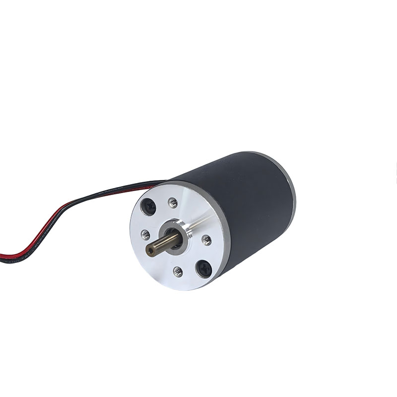
Brushed architectures rely entirely on mechanical commutation to switch the internal current direction. They use stationary physical brushes that press continuously against a rotating cylinder called a commutator. This direct mechanical contact constantly reverses the electrical current flow in the spinning rotor windings. It forces continuous rotation without requiring complex external electronics.
These units offer highly straightforward two-wire control. You simply apply a direct voltage to the positive and negative terminals. They do not require sophisticated drive electronics or microprocessors to spin. This drastically reduces initial procurement costs and simplifies wiring schematics. They also provide excellent starting torque immediately upon receiving power. You can rely on them for consistent low-speed performance under heavy initial friction loads.
Mechanical friction presents a significant engineering downside. Physical sliding contact leads to inevitable brush wear over time. You must plan for scheduled maintenance windows to replace worn carbon brushes. Furthermore, arcing at the contact points generates substantial Electromagnetic Interference (EMI). This electrical noise easily disrupts sensitive data signals in nearby communication lines.
Industrial environments frequently rely on standardized, heavy-duty form factors. Consider a robust Series 90 Brushed DC Motor. It highlights predictable performance in rugged applications. You specify this architecture when simplicity and cost-efficiency significantly outweigh maintenance concerns. It serves as a highly reliable DC Motor for straightforward mechanical actuation in environments that tolerate scheduled upkeep.
Best Practices: Implement ceramic filtering capacitors across the positive and negative terminals to suppress electrical noise at the source.
Common Mistakes: Deploying brushed units inside sealed or highly inaccessible locations where routine brush replacement becomes physically impossible.
Brushless designs eliminate mechanical commutators entirely from the system. They utilize rapid electronic commutation to manage current flow. The system frequently relies on embedded Hall effect sensors to determine exact rotor positioning. More advanced setups use sensorless algorithms to track back-electromotive force generated by the spinning magnets. The external controller then energizes specific stationary stator coils to drive the permanent magnet rotor smoothly.
Zero brush friction translates directly to a significantly longer operational lifespan. The absence of grinding carbon parts ensures zero airborne particulate generation. This inherent cleanliness makes them ideal for sealed cleanrooms, pharmaceutical labs, or sensitive medical environments. They deliver a markedly higher power-to-weight ratio compared to older mechanical counterparts. Superior thermal dissipation occurs naturally because the heat-generating coils reside on the static exterior housing, readily transferring heat to the ambient air. They easily handle continuous, ultra-high-speed operation without degrading.
You cannot run these units by simply connecting a standard battery. They require a specialized electronic speed controller (ESC) or advanced drive module to operate. This strict requirement increases both upfront procurement costs and overall system complexity. Integration demands rigorous software tuning, precise timing calibration, and extensive electronic design validation.
Precision applications demand immense power density in tight spaces. Evaluating an 80mm BLDC motor serves as an excellent benchmark for this capability. Dimensional constraints benefit immensely from this compact, sensor-driven architecture. Automated guided vehicles (AGVs), drones, and precision robotics rely extensively on these specific units for reliable, maintenance-free navigation.
Best Practices: Ensure the ESC firmware specifically matches the motor's internal pole count and maximum voltage parameters to prevent desynchronization.
Common Mistakes: Overlooking the active cooling requirements for the external controller unit itself, leading to thermal throttling during heavy use.
This distinct architecture marries a standard electric power unit with a dedicated mechanical gearhead. You can utilize either a brushed or brushless core as the primary driver. The attached gearbox features planetary, spur, or worm gear configurations. This physical integration permanently transforms the output characteristics at the final drive shaft, prioritizing force over raw speed.
A connected gearbox multiplies the output torque while proportionally reducing the operational shaft speed. You achieve massive rotational force without requiring a massively oversized electrical core. It consolidates mechanical space beautifully within the machine chassis. You avoid designing vulnerable external belt-and-pulley systems or complex, heavy chain reduction mechanisms.
You must evaluate several specific mechanical dimensions when specifying a Gear Motor.
Gearbox Efficiency: Factor in unavoidable power loss moving through the complex gear train. Planetary gears offer exceptional mechanical efficiency and handle high torque loads. Worm gears provide unique self-locking capabilities but suffer from noticeably lower mechanical efficiency.
Backlash and Precision: Assess the mechanical play inside the meshing teeth. High precision is absolutely crucial for exact positioning applications in robotic arms or automated CNC machinery.
Load Distribution: Determine if the internal bearings can handle the heavy radial and axial forces applied directly to the final output shaft during operation.
These specialized units excel in heavy industrial environments. They remain the ideal, straightforward choice for long conveyors, automated linear actuators, and heavy lifting mechanisms. Whenever sheer brute torque dictates the operational success of the system, mechanical gear reduction provides the most reliable and space-efficient solution.
Best Practices: Select a self-locking worm gear configuration if you strictly need the system to hold a heavy suspended load during sudden power failures.
Common Mistakes: Ignoring the maximum rated torque threshold of the gearbox, which quickly causes internal gear teeth to shear under heavy stall conditions.
You must approach the final hardware selection systematically. We recommend using a structured comparison framework to map your specific technical requirements against available architectures. This prevents costly redesigns late in the prototyping phase.
Use this evaluation matrix to narrow down your primary category based on operational priorities.
Priority Operational Need | Default Architecture Choice | Primary Trade-off |
|---|---|---|
Lowest initial procurement cost and simple two-wire integration | Brushed Architecture | Requires scheduled brush replacement and emits electrical noise |
Zero-maintenance operation, high RPM, and maximum efficiency | Brushless (BLDC) Architecture | Requires integrating complex external electronic speed controllers |
Moving massive mechanical loads within a highly compact space | Geared Architecture | Sacrifices maximum top speed and introduces slight mechanical backlash |
Assess the specific Ingress Protection (IP) ratings carefully for deployment in harsh environments. Units exposed to industrial dust, coolant spray, or moisture require fully sealed outer housings. Factor in EMI and RFI mitigation requirements extremely early in the design phase. This remains especially critical when avoiding brushed motor arcing near sensitive diagnostic sensors or wireless communication modules.
Move swiftly from theoretical selection to physical prototyping. Request comprehensive torque-speed performance curves from your hardware suppliers. We strongly recommend testing the physical units under simulated, worst-case load conditions. Real-world thermal mapping often reveals subtle integration flaws completely missed during initial software simulation.
The optimal motor type depends entirely on balancing acceptable long-term operational impact against your precise performance demands. Do not evaluate the motor in a vacuum. You must factor in the physical footprint of external controllers, expected maintenance downtime, and rigid spatial constraints inside the machine chassis. Engage directly with application engineers to validate your theoretical torque-speed requirements. Always request functional sample units to conduct rigorous thermal and dynamic load testing before finalizing your production design.
A: Focus heavily on internal wear mechanisms. Brushed units rely on physical friction. Their carbon brushes typically wear out between 1,000 and 3,000 hours, requiring manual replacement. Brushless units eliminate this mechanical contact entirely. Their operational lifespan is limited only by internal bearing wear, which frequently exceeds 10,000 hours of continuous use.
A: No, you cannot. A brushless unit absolutely requires electronic commutation to function. Direct application of a constant voltage will not rotate the rotor. A specialized electronic speed controller (ESC) must rapidly switch the current across the stator coils in a precise, timed sequence to induce continuous rotation.
A: Address the immediate physical size implications. A direct drive setup requires a massive physical footprint to achieve high torque at very low speeds. A geared setup achieves the exact same torque output in a fraction of the space. It utilizes a much smaller high-speed core connected to a mechanical reducer.
A: Mechanical brushes create continuous miniature sparks as they break and make contact with the spinning commutator. This electrical arcing generates significant radio frequency interference. Brushless units utilize silent electronic switching. They remain the mandatory choice for environments highly sensitive to electromagnetic interference, such as medical wards or advanced diagnostic equipment.


