close
Choose Your Site
Global
Social Media
Views: 0 Author: Site Editor Publish Time: 2026-07-27 Origin: Site
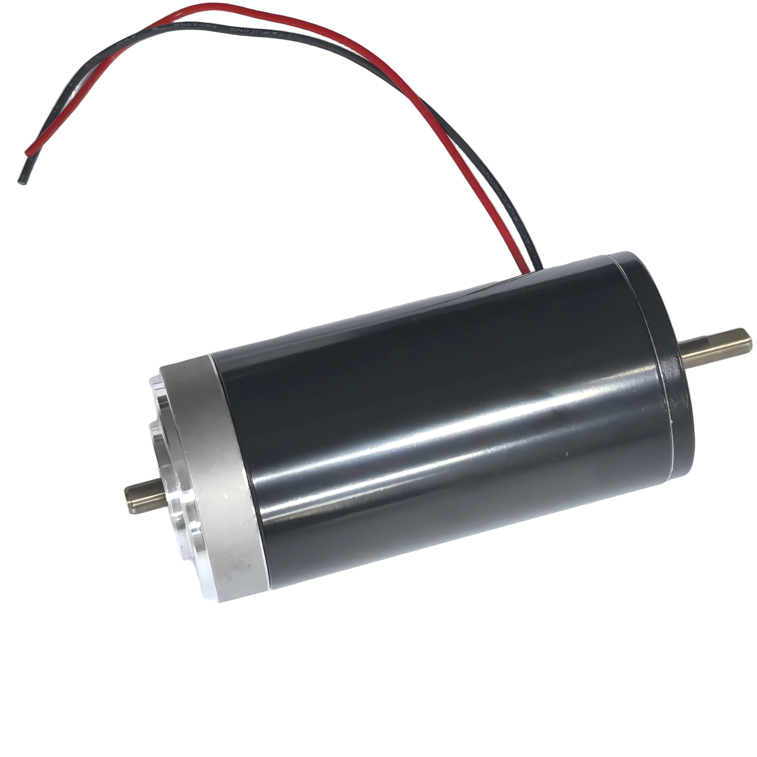
Despite the rapid adoption of brushless technologies, the mechanical commutation motor remains a highly specified component across manufacturing, automotive, and consumer engineering sectors. Engineering and procurement teams constantly face the challenge of balancing unit cost, drive circuitry simplicity, and high starting torque against the known maintenance lifecycle and physical limitations of mechanical brushes. This guide breaks down common industrial and commercial applications, establishes a technical evaluation framework, maps motor topologies to specific use cases, and outlines implementation risks. We will help you determine if a brushed architecture aligns with your project's performance requirements. A well-integrated Brushed DC Motor delivers reliable power without the overhead of complex electronic controllers.
Cost-to-Performance Dominance: Brushed motors require significantly less complex drive electronics compared to brushless alternatives, drastically reducing overall system CapEx.
Application Sweet Spots: They are the optimal choice for intermittent duty cycles, applications requiring high initial torque, and highly cost-sensitive consumer or automotive components.
Industrial Viability: A 24V industrial DC motor remains a highly viable solution in heavy-duty environments where maintenance accessibility is high and legacy control systems are already in place.
Known Trade-offs: Successful deployment requires proactive engineering mitigation for mechanical brush wear, thermal buildup, and electromagnetic interference (EMI).
Defining the operational thresholds where brushed technology outperforms alternatives requires a clear look at return on investment. Engineers specify these motors when the application demands immediate, high-torque output without the financial burden of advanced sensor arrays. The primary advantage lies in drive simplicity. Direct DC voltage operation eliminates the need for complex electronic commutation controllers or multi-phase inverter bridges. You apply voltage, and the motor spins. Reversing polarity reverses the direction. This straightforward electrical relationship drastically reduces component counts on printed circuit boards and minimizes potential points of failure in the control logic.
Torque characteristics further solidify their position in mechanical design. These motors feature a highly linear speed-torque curve. They deliver maximum torque at zero RPM, commonly referred to as stall torque. This characteristic proves invaluable for applications that must move heavy loads from a complete stop. Form factor flexibility also plays a critical role. Engineers can integrate these units into space-constrained assemblies where bulky external controllers would otherwise interfere with the mechanical housing.
Field maintenance teams benefit directly from this architecture. Troubleshooting requires only basic diagnostic tools. Technicians can perform simple voltage and current checks at the motor terminals to identify health issues. They do not need specialized software, digital logic probes, or hardware debuggers to determine if the motor or the power supply has failed.
Disconnect the motor from the primary power supply to ensure safety during testing.
Measure the resistance across the motor terminals using a standard multimeter to check for open windings.
Apply a low test voltage directly to the terminals to verify basic rotor movement and commutator contact.
Inspect the physical brush length and spring tension if the motor exhibits intermittent stalling.
Check the commutator surface for excessive pitting or carbon buildup that might cause electrical shorts.
Different internal wiring configurations yield vastly different performance profiles. Selecting the correct topology ensures the motor matches the mechanical load requirements. We see four primary configurations used across industrial and commercial designs.
Permanent Magnet (PMDC) Motors: These utilize permanent magnets to generate the stator field. They are ideal for compact, low-to-medium power applications like automotive accessories and medical devices. They offer a high torque-to-volume ratio and excellent efficiency within a small footprint.
Series-Wound DC Motors: Designed specifically for high starting torque. The field windings connect in series with the armature. This configuration allows massive current draw during startup, making them the standard choice for heavy traction equipment and starter motors.
Shunt-Wound DC Motors: Optimized for constant speed control. The field windings connect in parallel with the armature. They maintain a relatively stable speed regardless of load variations, serving well in industrial conveyors and heavy-duty fan systems.
Compound-Wound DC Motors: These blend the characteristics of series and shunt designs. They feature both series and parallel field windings. This hybrid approach delivers high starting torque while maintaining stable operating speed limits under variable loads.
Motor Topology | Stator Field Generation | Primary Advantage | Common Application |
|---|---|---|---|
Permanent Magnet (PMDC) | Permanent Magnets | High efficiency, compact size | Automotive accessories, medical pumps |
Series-Wound | Electromagnet (Series) | Maximum starting torque | Winches, traction vehicles, starters |
Shunt-Wound | Electromagnet (Parallel) | Constant speed under load | Conveyor belts, industrial fans |
Compound-Wound | Electromagnet (Hybrid) | High torque with speed limits | Elevators, heavy stamping presses |
Modern vehicles rely heavily on mechanical commutation for auxiliary functions. Specific applications include power windows, motorized seat adjusters, windshield wipers, steering column adjusters, and automated mirrors. The evaluation lens here focuses on intermittent duty cycles. These mechanisms operate for only a few seconds at a time. Leveraging the high reliability of Permanent Magnet designs for short durations perfectly matches the extreme cost-sensitivity of high-volume automotive manufacturing. The motors spend most of their operational life idle, meaning brush wear is negligible over the lifespan of the vehicle. You will rarely see a power window motor fail due to worn brushes; usually, the mechanical regulator breaks first.
Factory floors utilize these motors for rugged, straightforward motion control. Common applications include conveyor belts, paper machines, heavy-duty linear actuators, tensioning systems, and legacy automated guided vehicles. Deploying a 24V industrial DC motor ensures seamless integration with existing industrial control panels. Plant engineers prioritize straightforward speed adjustment via simple analog voltage modulation. The rugged physical design withstands harsh factory environments, while the standardized voltage aligns with standard industrial power supplies. When a jam occurs on a sorting line, the simple control architecture allows operators to quickly reverse the motor and clear the obstruction without resetting complex digital drives.
Moving massive weight requires immense initial force. Material handling equipment, golf carts, electric winches, motorized wheelchairs, and mobile robotics depend on this technology. Utilizing a series-wound, high power brushed DC motor delivers the raw starting torque required to move heavy loads from a dead stop. This architecture achieves massive mechanical output without relying on complex sensor arrays or expensive closed-loop feedback systems. The motor naturally draws the exact current needed to overcome the initial inertia. For example, an electric winch pulling a stuck vehicle out of mud relies entirely on the series-wound motor's ability to handle massive current spikes without stalling.
The consumer market demands performance at strict price points. Household appliances like blenders and vacuums, alongside cordless drills, lawnmowers, and motorized toys, heavily feature this technology. Product designers must balance the cost-effectiveness of a compact brushed drive motor against battery life expectations and physical weight restrictions. The simplicity of the motor allows manufacturers to allocate budget to better battery cells or improved ergonomic housings while still delivering the necessary cutting or driving torque. A cordless drill uses a simple trigger switch to modulate voltage, providing intuitive speed control for the user without requiring an onboard microprocessor.
Controlling mechanical commutation requires selecting the right electrical drive method based on application demands. You must match the drive circuit to the required mechanical output.
Direct-on-Line (DOL) Drive: This utilizes basic switches, relays, or contactors to supply full DC voltage directly to the terminals. It is highly effective for constant-speed, low-duty applications where soft starting is unnecessary.
Pulse-Width Modulation (PWM) Control: This implements basic H-bridge circuits or discrete MOSFET switches to vary the average voltage across the motor. PWM enables highly efficient speed control and soft-starting capabilities without dissipating excess power as heat.
Bi-Directional Drive (H-Bridge): Utilizing integrated H-bridge drivers or discrete transistor configurations allows the system to reverse voltage polarity instantly. This enables the rapid direction changes required in automotive windows and robotic actuators.
Linear Drive Amplifiers: Deploying linear regulators drives precision analog systems. Engineers select this topology when low electromagnetic noise is prioritized over raw power efficiency, typically in sensitive laboratory or audio equipment.
Successful integration requires evaluating physical limitations against environmental realities. Commutation mechanics dictate operational boundaries. Physical brushes made of carbon, graphite, or precious metals slide against copper commutator segments. This mechanical contact generates friction and electrical arcing. Consequently, engineers must avoid specifying these motors in highly explosive environments, as the sparking can ignite volatile gases or dust. Fully sealed enclosures can mitigate this, but they complicate thermal management.
Scalability and power density also drive specification decisions. Evaluating the physical size-to-power ratio is critical when scaling from fractional horsepower units in medical pumps to multi-horsepower industrial winch motors. The physical size of the commutator and brush assembly must grow proportionally to handle higher current loads, which eventually limits the maximum power density compared to electronically commutated alternatives. You have to account for the physical space required for brush replacement access doors on larger industrial units.
Regulatory compliance shapes the final product design. Engineering teams must navigate industry-standard evaluation lenses for safety, noise, and efficiency in specific geographic markets. Achieving CE, RoHS, and UL listings often requires adding specific external components to manage the electrical noise and thermal output inherent to mechanical commutation. You cannot simply drop a bare motor into a consumer product and expect it to pass FCC emissions testing without proper filtering.
Evaluating the financial impact requires looking beyond the initial purchase order. Calculating the long-term cost of brush replacement and maintenance downtime must be weighed against the immediate savings on motor and controller procurement. For applications running continuously 24/7, the cost of replacing brushes and resurfacing commutators will quickly surpass the initial savings. However, for intermittent applications, the brushes will likely outlast the mechanical life of the surrounding equipment, making the initial CapEx savings a permanent financial victory.
A side-by-side decision matrix comparing mechanical against electronic commutation clarifies the path forward. Evaluate the duty cycle first. Continuous operation heavily favors brushless designs, while intermittent operation favors brushed. Next, assess operational lifespan requirements and maintenance access. If a motor is buried deep inside a machine where brush replacement takes hours of teardown, mechanical commutation poses a risk. Finally, environmental constraints dictate feasibility. Cleanroom environments cannot tolerate the carbon dust generated by brush wear.
Proactive engineering prevents premature field failures. Managing mechanical wear requires specific strategies. Engineers must predict the brush lifecycle based on the expected duty cycle and load profile. Selecting appropriate brush materials based on current density is vital. High-current applications require copper-graphite blends, while low-current signal motors use precious metals. Furthermore, designers must manage carbon dust buildup inside the motor housing to prevent internal short circuits across the commutator segments.
Thermal management directly impacts performance and longevity. Heat generates rapidly at the commutator-brush interface due to friction and electrical resistance. Designing adequate ventilation, heat sinking, or active cooling becomes necessary in enclosed spaces. If the motor operates near its stall torque frequently, thermal overload protection must be integrated into the control circuit. You should specify thermal thermistors embedded in the stator windings to cut power before the insulation melts.
Suppressing Electromagnetic Interference (EMI) is non-negotiable for regulatory compliance. The mechanical switching of coils creates significant electrical noise. Implementing suppression capacitors across the motor terminals and to the chassis provides a low-impedance path for high-frequency noise. Adding choke inductors in series with the power leads and utilizing shielded cables further mitigates the electrical noise, ensuring compliance with EMC directives.
Verify your exact duty cycle requirements to ensure intermittent operation aligns with expected brush lifespans.
Assess environmental constraints, specifically checking for explosive gases, heavy moisture, or strict cleanroom dust limitations.
Initiate thermal and EMI testing on early mechanical prototypes to size suppression capacitors and heat sinks accurately.
Audit supplier quality specifically regarding brush material composition and commutator copper grade.
A: They can handle continuous operation, but require scheduled maintenance to replace worn brushes and clean carbon dust. For 24/7 industrial use without maintenance access, brushless alternatives are generally preferred to avoid downtime.
A: PMDC motors excel in compact, low-to-medium power applications requiring high efficiency. Wound-field motors, particularly series-wound, are utilized for heavy-duty applications demanding massive starting torque, such as traction and winches.
A: Brush lifespan varies heavily based on load, speed, and operating environment. Typically, industrial brushes last between 2,000 and 5,000 operating hours before requiring replacement, assuming proper thermal management.
A: The most cost-effective method is a Direct-on-Line (DOL) drive using heavy-duty contactors or relays. If variable speed is required, a basic Pulse-Width Modulation (PWM) controller utilizing discrete MOSFETs offers the best balance of cost and efficiency.
A: Solder ceramic suppression capacitors directly across the motor terminals and from each terminal to the motor casing. Additionally, twist the power supply wires and use ferrite beads to suppress high-frequency electrical noise.
A: Power seats operate for only a few seconds per month. The extreme intermittent duty cycle means brush wear is irrelevant. Brushed motors eliminate the need for expensive electronic controllers, drastically reducing the vehicle's manufacturing cost.
A: Standard brushed motors are generally unsafe for explosive environments due to continuous arcing at the commutator. They must be housed in specialized, certified explosion-proof enclosures to prevent sparks from igniting surrounding volatile gases.