close
Choose Your Site
Global
Social Media
Views: 0 Author: Site Editor Publish Time: 2026-09-15 Origin: Site
Despite the aggressive market push toward brushless technologies, the traditional brushed dc motor remains a foundational, cost-effective component in thousands of industrial and commercial applications. Engineers and procurement teams frequently encounter a critical decision point when specifying motion control systems. Specifying the wrong motor type or misunderstanding the mechanical wear limits of carbon brushes leads to unplanned downtime, premature commutator failure, and inflated operational maintenance expenses.
To make an informed procurement or engineering decision, buyers must understand exactly how motor brushes function. You need to evaluate the maintenance liabilities they introduce and understand how to match specific motor classes against precise operational requirements. This guide breaks down the mechanics of internal commutation, the realities of brush wear, and the technical criteria for selecting the correct motor frame size for your application.
Component Function: A motor brush is a conductive block (typically specially prepared carbon or graphite) that creates a continuous electrical pathway between the electrified stationary power source and the rotating parts of the motor.
Maintenance Reality: Brush wear is inevitable; predictable maintenance schedules and physical inspections are required to prevent catastrophic commutator damage and electrical arcing.
Specification Logic: Selecting a brushed DC motor over a brushless alternative is justified by lower upfront costs, simpler control electronics, and high starting torque.
Scalability: Motor selection must be matched to load requirements, with distinct form factors (e.g., Series 42, Series 60, Series 90) dictating continuous torque, thermal dissipation, and physical footprint.
A motor brush is not a brush in the traditional sense of bristles. It is a solid, highly engineered block of conductive material designed to slide against a rotating surface. The primary function of this component is to transfer electrical current from the stationary power supply to the spinning armature. Manufacturers formulate these blocks from specific material grades to balance electrical conductivity with mechanical friction. The engineering challenge lies in creating a material soft enough to prevent wearing down the copper commutator, yet hard enough to survive thousands of hours of continuous friction.
Standard industrial applications typically utilize electrographite brushes. Manufacturers create electrographite by baking carbon at extremely high temperatures, which alters its molecular structure. This material offers excellent thermal stability and self-lubricating properties, which help preserve the commutator surface. For high-current or low-voltage applications, engineers specify metal-graphite composites. These blends incorporate copper or silver to drastically lower electrical resistance. The exact composition directly influences how well the motor handles heavy loads and how long the internal components survive under continuous operation.
Brush Material Grade | Primary Composition | Best Application Environment | Conductivity Level |
|---|---|---|---|
Carbon Graphite | Natural graphite and amorphous carbon | Low-speed, fractional horsepower motors | Moderate |
Electrographite | High-temperature treated carbon | Standard industrial, high-voltage applications | High |
Metal Graphite | Graphite mixed with copper or silver powder | High-current, low-voltage traction motors | Very High |
Silver Graphite | Graphite heavily saturated with silver | Precision signal transmission, tachometers | Maximum |
To generate continuous rotational torque, the magnetic field within the motor must constantly shift. Brushed motors achieve this mechanically rather than electronically. The brushes press firmly against the commutator, a cylindrical structure composed of multiple copper segments separated by insulating mica. As the rotor spins, the brushes slide across these segments, acting as a dynamic bridge for the electrical current.
This sliding action sequentially energizes different coils within the armature windings. The mechanical contact physically reverses the direction of the electrical current at the exact right moment during rotation. This internal commutation process forces the magnetic fields of the rotor to constantly chase the stationary magnetic fields of the stator. Because this timing is entirely mechanical and dictated by the physical geometry of the commutator, the motor requires no external electronic controllers to spin. You simply apply direct current, and the internal geometry handles the phase switching automatically.
Maintaining optimal electrical contact requires precise mechanical pressure. The brush holder assembly houses the carbon block, keeping it perfectly aligned with the curvature of the commutator. These holders are typically machined from brass or molded from high-temperature thermoset plastics to ensure dimensional stability under thermal stress. Inside this holder, a spring applies constant downward force on the brush.
Spring tension is a critical engineering variable. Industrial standards usually dictate a spring pressure between 2.0 and 4.0 PSI depending on the brush grade and motor speed. If the tension is too high, mechanical friction increases exponentially, causing rapid brush wear and excessive heat generation. If the tension is too low, the brush bounces off the commutator at high speeds. This micro-bouncing breaks the electrical circuit momentarily, drawing electrical arcs that pit and destroy the copper segments. Over time, heat and vibration degrade spring steel. Loss of tension directly impacts motor efficiency and accelerates catastrophic failure.
Mechanical commutation relies on physical contact, which inherently introduces friction. This friction generates localized heat at the brush-commutator interface. Engineers must account for this thermal load when designing enclosures and duty cycles. Beyond friction, the electrical transfer itself creates challenges. As the brush transitions from one commutator segment to the next, it momentarily shorts the adjacent coils.
This transition generates an inductive kickback, often visible as minor sparking or electrical arcing. While a small amount of trailing-edge sparking is normal, excessive arcing indicates a severe mechanical or electrical misalignment. Severe arcing acts like a microscopic plasma torch. It melts the copper commutator bars, transfers material across the insulation gaps, and drastically reduces the energy converted into usable torque. Managing this interface through proper brush seating and spring tension is the most critical aspect of brushed motor reliability.
Carbon brushes are consumable components by design. Under optimal conditions, a standard industrial brushed motor will deliver between 2,000 and 5,000 hours of continuous operation before requiring brush replacement. However, real-world operational realities rarely match laboratory baselines. Facility managers must understand the variables that alter this timeline.
Frequent start-stop cycles, aggressive load variations, and extended periods of high-torque demand will accelerate carbon degradation. Environmental factors play an equally significant role. Carbon brushes rely on a microscopic film of moisture and copper oxide on the commutator to act as a lubricant. This is known as the patina. In extremely low-humidity environments, such as high-altitude installations or winterized warehouses, this film fails to form. Without this lubricating film, the raw carbon grinds against the raw copper, leading to rapid brush dusting where a brush can wear out in a matter of days. Conversely, high-dust environments introduce abrasive particles into the sliding interface, grinding away both the brush and the commutator.
The physical realities of mechanical commutation restrict where these motors can be deployed. As the carbon block wears down, it sheds fine conductive dust. This carbon dust accumulates inside the motor housing and can short out internal components if not properly vented or cleaned. This characteristic makes standard brushed motors entirely unsuitable for cleanroom environments, semiconductor manufacturing, or optical assembly facilities.
Furthermore, the continuous electrical arcing at the commutator generates significant Electromagnetic Interference (EMI) and Radio Frequency Interference (RFI). This electrical noise can disrupt nearby sensitive sensors, communication equipment, or medical electronics unless heavily shielded with external capacitors and grounded enclosures. Finally, the presence of open sparks means standard brushed motors cannot operate safely in explosive atmospheres or highly flammable chemical processing areas without specialized, heavy explosion-proof enclosures.
Selecting the correct motor requires aligning mechanical output with spatial and thermal realities. Engineers evaluate several core dimensions during the specification phase. Continuous torque dictates the load the motor can handle indefinitely without overheating. Peak torque defines the maximum momentary force available to overcome initial inertia or temporary jams. You must map these torque requirements against the thermal time constant of the motor frame.
RPM requirements and voltage inputs must match the available power supply and gearing ratios. Spatial constraints often dictate the final frame size. A motor must fit within the machine envelope while retaining enough surface area to dissipate the heat generated by internal commutation. Matching these criteria to standard frame series ensures optimal performance and manageable maintenance schedules.
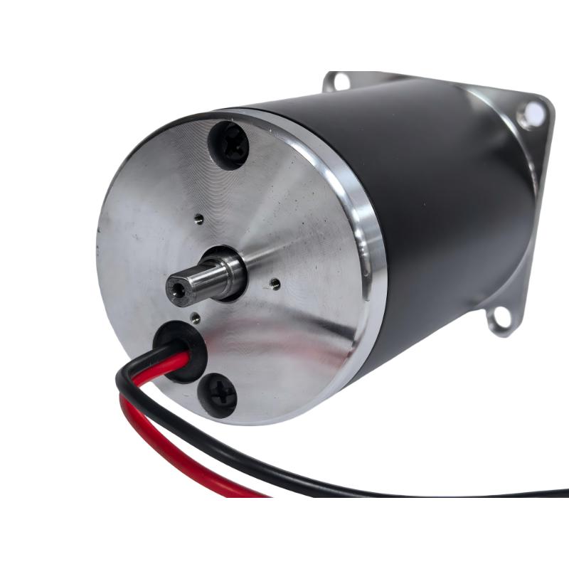
The series 42 brushed dc motor represents a compact solution for applications constrained by tight physical boundaries. It delivers moderate torque suitable for precision tasks where space is the primary limiting factor.
Application Profile: This frame size frequently powers medical devices, small automation actuators, motorized valves, and portable power tools. It excels where space is at a premium but reliable starting torque is still necessary to initiate movement against a static load.
Evaluation Lens: When specifying this series, engineers must focus heavily on thermal management. Because the physical footprint is small (typically around 42mm in diameter), the motor has less surface area to shed heat. Confined installations require careful duty-cycle planning to prevent the internal temperatures from degrading the brush springs or melting the winding insulation. You must ensure adequate ambient airflow around the housing.
Stepping up in size, the series 60 brushed dc motor serves as the mid-range workhorse for general industrial applications. It balances physical size with substantial mechanical output, making it highly versatile for factory automation.
Application Profile: You will find this series driving industrial conveyors, packaging equipment, automated guided vehicles (AGVs), and heavy-duty robotics. It handles continuous duty cycles effectively and provides enough torque to move substantial material loads across a factory floor.
Evaluation Lens: Assess integration flexibility when looking at this frame. Standard mounting configurations make it easy to swap into existing machinery. Evaluate the continuous duty capabilities against your load profile. This size offers better heat dissipation, allowing for longer run times under moderate to heavy loads without premature brush failure. Pay attention to the shaft diameter and bearing load ratings when coupling this motor to gearboxes or pulleys.
For demanding, high-load environments, the series 90 brushed dc motor provides rugged construction and massive starting torque. The larger frame accommodates thicker windings, robust bearings, and heavier carbon brushes designed for high-amp draws.
Application Profile: This motor drives heavy material handling equipment, large fluid pumps, traction systems, and industrial winches. It is built to overcome massive initial inertia and sustain high torque output even when the system experiences sudden mechanical resistance.
Evaluation Lens: Evaluate the heat dissipation characteristics under maximum load. The larger surface area handles thermal spikes better than smaller frames. Crucially, assess the accessibility of the brush inspection ports. Because these motors handle extreme loads, brush wear is a major factor. Easy access for on-site maintenance prevents extended downtime during routine brush swaps. Ensure the mounting brackets can handle the significant torsional forces this motor generates during startup.
Failing brushes broadcast clear warning signs before catastrophic motor failure occurs. Operators and maintenance personnel must recognize these symptoms early. The most obvious indicator is excessive sparking visible through the motor vents. While a faint blue trail is normal, bright yellow or orange sparks indicate severe arcing and poor contact. This often means the brush is bouncing or the commutator is out of round.
Operational symptoms include erratic motor speeds, sudden drops in torque under load, and a failure to start without manual assistance. You may also notice unusual acoustic noise, such as a harsh grinding or chattering sound, which occurs when the brush spring loses tension or the carbon wears down to its metal shunt wire. Physical inspection will reveal a shortened carbon block that no longer applies adequate pressure to the commutator. If the motor smells like burning ozone or hot metal, shut it down immediately for inspection.
Replacing carbon brushes is a straightforward procedure that prevents expensive equipment failure. Follow a strict mechanical protocol to ensure the new brushes seat correctly and operate efficiently.
Isolate Power: Completely disconnect the motor from all electrical sources and apply standard lockout/tagout procedures. Verify zero voltage with a multimeter before touching the housing.
Access the Holder: Remove the external brush caps or access panels. Carefully extract the brush assembly, noting the orientation of the carbon block. Do not pull on the fragile shunt wire.
Evaluate Components: Measure the remaining carbon against the manufacturer's minimum wear line. Inspect the spring for discoloration or loss of tension, which indicates heat damage. If the spring is blued from heat, replace the entire holder assembly.
Inspect the Commutator: Shine a light onto the copper segments. Look for deep grooving, uneven wear patterns, or burned mica insulation. The surface should have a smooth, uniform chocolate-brown film. If you see raw, bright copper, the patina has been stripped away.
Seat the New Brushes: Insert the new brushes. If the commutator is slightly worn, use a specialized seating stone to gently shape the face of the new carbon brush to match the exact radius of the commutator. Run the motor at no load for 30 minutes to allow the brushes to wear in and establish a new patina before applying full mechanical load.
Ignoring brush maintenance transforms a minor consumable expense into a major capital loss. When a carbon brush wears past its limit, the embedded copper shunt wire or the steel tension spring makes direct contact with the spinning commutator. This metal-on-metal friction acts like a lathe.
It instantly scores deep grooves into the soft copper segments. Once the commutator is severely damaged, simply dropping in new brushes will not fix the motor. The new brushes will chip and shatter against the damaged copper. At this stage, the entire motor must be removed and sent to a machine shop. A technician must turn the commutator on a lathe to restore a smooth surface and then manually undercut the mica insulation between each copper bar. If the damage is too deep, the motor must be scrapped entirely. Deferring a basic inspection guarantees expensive mechanical failure.
Reactive maintenance—waiting for the motor to spark or stall—is an inefficient strategy. Engineering teams must establish preventative maintenance intervals based on actual operational data. Do not rely solely on calendar dates, as motor usage varies wildly between production shifts.
Track the specific duty cycle, load conditions, and environmental factors of each installation. A motor operating in a hot, dusty facility will require inspections twice as often as the identical motor running in a climate-controlled warehouse. Baseline the wear rate by inspecting a new motor after its first 500 hours of operation. Measure the brush length, calculate the wear rate per hundred hours, and schedule future replacements long before the carbon reaches its critical minimum length. Implement a digital maintenance log to track these measurements across your entire facility.
The primary advantage of specifying a brushed motor is the significantly lower initial purchase price. The internal mechanical commutation eliminates the need for expensive rare-earth magnets on the rotor and complex internal sensor arrays. For projects with strict initial capital constraints, this makes brushed technology highly attractive. You can procure a high-torque brushed motor for a fraction of the cost of an equivalent brushless servo system.
However, engineers must balance this low entry price against lifecycle maintenance requirements. Over a 5-to-10-year operational lifecycle, a brushed motor requires physical inspections, replacement parts, and labor hours. If the motor is installed in an inaccessible location—such as deep inside a complex machine chassis or high on a factory ceiling—the labor cost to access and replace the brushes will quickly exceed the initial savings. You must factor in the physical accessibility of the installation site during the design phase.
Brushed DC motors offer unmatched simplicity in control integration. Because commutation happens mechanically, you can operate these motors directly from a standard DC power supply. Reversing the motor direction simply requires reversing the polarity of the input voltage using a basic relay or a manual Double-Pole Double-Throw (DPDT) switch.
This simplicity drastically reduces integration risks, especially when retrofitting legacy systems or designing basic automation equipment. You do not need to program complex Electronic Speed Controllers (ESCs) or manage feedback loops from Hall-effect sensors. A basic Pulse Width Modulation (PWM) controller is entirely sufficient for precise speed regulation. This reduces the overall component count, minimizes potential points of failure in the electrical cabinet, and allows maintenance electricians to troubleshoot the system with nothing more than a standard multimeter.
Evaluating the correct motor technology requires a clear comparison of operational parameters. Use the following matrix to guide your specification process.
Evaluation Criteria | Brushed DC Motor Advantage | Application Considerations |
|---|---|---|
Starting Torque | Exceptionally high starting torque due to direct current flow to the armature. | Ideal for heavy loads, winches, and traction systems requiring immediate force. |
Control Electronics | Requires only basic DC power or simple PWM controllers. No complex programming. | Perfect for legacy system retrofits and cost-sensitive automation designs. |
Maintenance Demands | Requires scheduled physical inspections and consumable brush replacements. | Must ensure the motor is physically accessible for routine service intervals. |
Environmental Tolerance | Vulnerable to extreme dust, vacuum environments, and explosive atmospheres. | Best suited for standard industrial environments with adequate ventilation. |
Wiring Complexity | Simple two-wire connection for power and ground. | Reduces cable routing issues in moving machinery and robotic arms. |
Brushed DC motors remain a highly viable, robust solution for applications demanding high starting torque, straightforward control electronics, and strict control over initial capital expenditure. As long as the operational environment tolerates mechanical commutation and facility managers commit to routine maintenance, these motors deliver decades of reliable service.
To finalize your motor specification, take the following actionable steps:
Audit your exact continuous and peak torque requirements to ensure you do not undersize the motor, which leads to rapid brush burnout.
Match your physical space and thermal constraints to the appropriate frame size, evaluating the specific benefits of Series 42, 60, or 90 architectures.
Review the manufacturer's data sheets to confirm maximum RPM limits and recommended duty cycles for your chosen frame.
Design your machine layout to guarantee unobstructed access to the motor's brush caps, ensuring maintenance teams can perform future inspections safely and quickly.
Consult with an application engineer to verify that your operating environment will not degrade the carbon brushes prematurely due to extreme humidity or airborne contaminants.
A: Motor brushes are solid conductive blocks typically made from specially prepared carbon, graphite, or electrographite. For high-current or low-voltage applications, manufacturers use metal-graphite composites containing copper or silver. These materials are engineered to provide high electrical conductivity while maintaining low friction and self-lubricating properties against the copper commutator.
A: In standard industrial applications, carbon brushes typically last between 2,000 and 5,000 hours of continuous operation. However, this lifespan varies drastically based on the load profile, duty cycle, and environment. High friction, extreme temperatures, abrasive dust, and very low humidity will significantly accelerate brush wear and shorten this timeline.
A: First, safely isolate and disconnect all power. Remove the external brush caps or access panels on the motor housing. Pull out the brush holder assembly and measure the remaining carbon length against the manufacturer's wear line. Check the spring tension, inspect the commutator for grooving, and insert the new brushes, ensuring they seat properly against the commutator curve.
A: When brushes wear past their limit, they lose consistent electrical contact with the commutator. This causes erratic motor performance, sudden loss of torque, and excessive sparking. If the carbon wears down completely, the metal spring or shunt wire will grind directly against the commutator, causing severe, often irreversible mechanical damage to the copper segments.
A: Look for operational symptoms such as a sudden loss of power, erratic rotational speeds, or failure to start under load. Visual indicators include excessive yellow or orange sparking visible through the cooling vents. Auditory clues include harsh chattering or grinding noises. A physical inspection revealing short carbon blocks confirms replacement is necessary.
A: No. A brushed DC motor cannot function without brushes. The brushes act as the critical physical bridge that transfers electrical current from the stationary power supply to the rotating armature. Without them, the internal commutation circuit remains open, no magnetic field is generated in the rotor, and the motor will not spin.
A: Yes, they are widely used. Brushed motors remain the preferred choice for cost-sensitive projects, heavy-duty applications requiring massive starting torque, and legacy system retrofits. Their ability to operate on simple DC power without complex electronic speed controllers makes them highly reliable and easy to integrate into straightforward industrial automation systems.