close
Choose Your Site
Global
Social Media
Views: 0 Author: Site Editor Publish Time: 2026-07-14 Origin: Site
Specifying the wrong motor technology for a motion control system inevitably leads to compromised precision, thermal failures, or unnecessary controller costs. Engineering and procurement teams must balance positional accuracy, speed requirements, and budget constraints when designing automation, robotics, or manufacturing equipment. You cannot simply swap one motor type for another without fundamentally altering the mechanical linkage and the electronic control architecture. This guide breaks down the fundamental mechanical and electrical differences between a stepper motor and a standard DC motor. We provide a technical evaluation framework to ensure you specify the correct drive system for your application's exact success criteria, focusing on torque curves, thermal management, and positional feedback requirements.
Control Methodology: Stepper motors excel in precise, open-loop positional control using discrete electrical pulses, whereas DC motors are designed for continuous rotation driven by direct voltage.
Torque vs. Speed Trade-off: Steppers deliver maximum holding torque at zero or low speeds but lose torque rapidly as speed increases; DC motors maintain consistent torque across a much wider speed range.
System Complexity: While a basic brushed DC motor requires minimal control electronics, both stepper motors and brushless DC (BLDC) motors require specialized drivers or controllers to manage phase switching and feedback.
Thermal Realities: Stepper motors draw full current even when stationary to maintain holding torque, requiring strict thermal management, whereas DC motors only draw current proportional to the mechanical load.
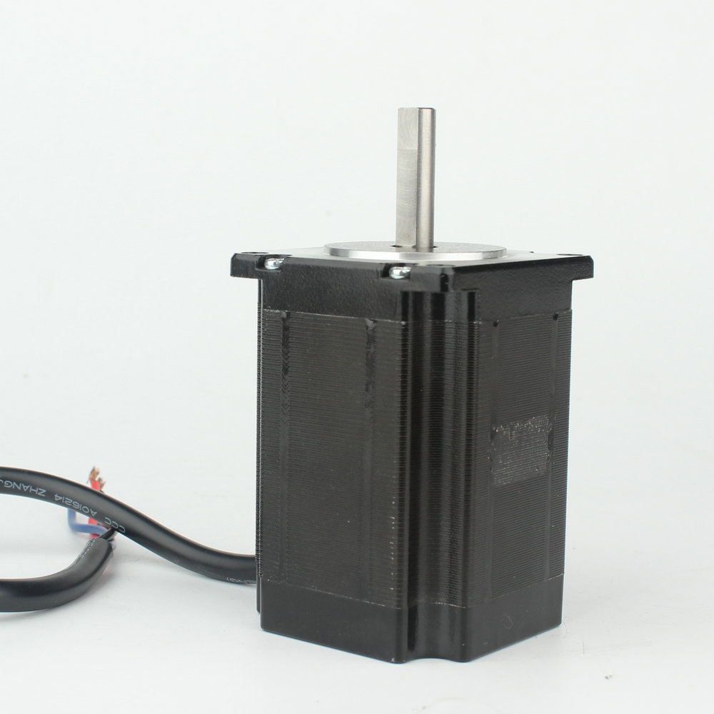
A Stepper Motor operates on the principle of magnetic alignment. The internal construction typically consists of a central rotor equipped with permanent magnets or a variable reluctance iron core. Surrounding this rotor is a stator housing multiple electromagnets arranged in distinct phases. When a motor driver sends current through these stator coils in a specific sequence, the rotor aligns itself with the magnetic field. This alignment happens in discrete steps.
Standard industrial steppers often feature a 1.8-degree step angle, meaning it takes exactly 200 electrical pulses to complete one full 360-degree mechanical revolution. High-resolution variants might use a 0.9-degree step angle for 400 steps per revolution. Because the controller dictates the exact number of pulses, the system knows the rotor's theoretical position without needing an external sensor. Technically, this makes the stepper a specialized high-pole-count brushless motor optimized specifically for static positioning and low-speed torque rather than continuous high-speed rotation. The rotor inertia is kept relatively low to allow for rapid starting, stopping, and reversing.
Engineers must account for the motor's inductance. High coil inductance limits how fast current can build up in the windings, which directly restricts the maximum stepping rate. To overcome this, modern drivers use chopper circuits that apply a voltage much higher than the motor's nominal rating to force current into the coils rapidly, cutting it off once the target current is reached.
A standard DC motor is built for continuous rotation. When you apply a direct current across its terminals, the motor spins. In traditional brushed designs, the stator contains permanent magnets, while the rotor (armature) houses the electromagnets. A mechanical commutator and carbon brushes handle the switching of the current direction in the rotor coils as it spins, ensuring the magnetic fields constantly push against the stator magnets.
Electronic commutation replaces these physical brushes in brushless variants. Instead of a mechanical switch, a microcontroller reads the rotor's position—often via Hall effect sensors—and fires the stator coils in the correct sequence. Speed control in both types relies on adjusting the applied voltage. In modern applications, we achieve this using Pulse-Width Modulation (PWM), rapidly turning the power on and off to simulate a lower average voltage. Torque, on the other hand, is directly proportional to the current drawn by the motor. If you apply a heavier mechanical load to the shaft, the motor slows down slightly, back electromotive force (EMF) drops, and the motor pulls more current from the supply to generate the torque needed to overcome the load.
The primary advantage of a stepper system is open-loop accuracy. You command the motor to move 1000 steps, and assuming the mechanical load does not exceed the motor's torque capacity, it moves exactly 1000 steps. You do not need an encoder for basic positioning. However, if a physical obstruction blocks the load, the motor will stall, the controller will continue sending pulses, and the system will lose its positional reference.
Achieving precise stopping and holding with a DC motor requires a closed-loop servomechanism. You must attach a rotary encoder to the shaft. The controller reads the encoder pulses, calculates the error between the target position and the actual position, and adjusts the PWM signal to drive the error to zero. This requires tuning PID (Proportional, Integral, Derivative) control loops, adding significant software and hardware complexity.
To enhance stepper resolution and reduce mechanical resonance, engineers utilize microstepping. By proportioning the current between two adjacent stator phases, the driver can hold the rotor in intermediate positions. A standard 1.8-degree motor driven at 16x microstepping requires 3,200 pulses per revolution, resulting in significantly smoother rotation and less vibration at low speeds.
Torque curves dictate motor selection. A DC Stepper Motor dominates low-speed applications. It provides its absolute maximum torque when the shaft is stationary (holding torque). As rotational speed increases, the inductance of the coils prevents the current from reaching its peak before the next step pulse arrives. Consequently, stepper torque drops off a cliff at higher RPMs. If you try to run a stepper too fast under load, it will stall.
DC motors exhibit a much flatter torque curve. They provide excellent high-speed performance and dynamic acceleration. A brushed or brushless DC motor can spin at thousands of RPMs while maintaining useful torque. They do not lose synchronicity. If a DC motor encounters a heavy load at high speed, it simply draws more current and slows down, whereas a stepper motor will violently stall and emit a high-pitched squeal.
Performance Metric | Stepper Motor | DC Motor (Brushed/Brushless) |
|---|---|---|
Holding Torque | Maximum at 0 RPM | Requires mechanical brake or active servo control |
High-Speed Torque | Poor (Rapid drop-off) | Excellent (Maintains torque at high RPM) |
Positional Control | Native open-loop (Steps) | Requires closed-loop encoder feedback |
Current Draw | Continuous (Even when idle) | Proportional to mechanical load |
Resonance Risk | High at specific low frequencies | Low to None |
Thermal management dictates the physical integration of the motor into your machine. Stepper motors draw continuous current at a standstill to maintain their holding torque. All that electrical energy converts directly into heat. It is entirely normal for a stepper motor casing to reach 80°C during standard operation. You must mount them to thermally conductive metal brackets to act as heatsinks. If you enclose a stepper motor in a plastic housing without ventilation, it will melt the housing or degrade its internal winding insulation.
DC motors are far more thermally efficient in variable-load applications. They only draw the current necessary to perform the mechanical work. If a DC motor is spinning freely with no load, it draws minimal current and generates very little heat. They can run continuously at their rated speeds without overheating, provided the ambient temperature and mechanical load remain within the manufacturer's specifications.
These motors are the backbone of automated equipment requiring predictable, repetitive movements. You will find them driving the axes of 3D printers, CNC routers, automated camera sliders, medical dosing pumps, and motorized precision dials. You choose this technology when exact repeatability and low-speed torque are non-negotiable. The open-loop nature saves significant costs on encoders and complex servo drives. However, you must engineer the mechanical system to ensure the load never exceeds the motor's pull-out torque, or you risk missed steps and ruined workpieces.
The Series 63 Brushed DC Motor represents a robust, classic design. These are deployed in conveyor belts, basic winches, automotive windshield wipers, and consumer appliances. You specify a brushed motor for maximum simplicity. You apply voltage, and it spins. Reversing the polarity reverses the direction. They offer continuous high-speed rotation where precise positional holding is irrelevant. The initial hardware cost is extremely low, and the control electronics can be as simple as a mechanical relay or a basic H-bridge circuit.
A 60mm BLDC motor is specified for high-performance applications like multi-rotor drones, industrial automation spindles, medical ventilators, and automated guided vehicles (AGVs). You choose BLDC technology when you need high rotational speed, exceptional power density, and a long lifespan unhindered by carbon brush wear. The trade-off is the mandatory inclusion of an electronic speed controller (ESC) or a sophisticated servo drive to handle the electronic commutation.
The electronic architecture required to drive these motors varies drastically. Brushed DC motors utilize simple H-Bridge circuits consisting of four MOSFETs to control direction and PWM for speed. The logic is straightforward and requires minimal processing power.
Stepper motors require dedicated indexer or translator drivers. The microcontroller sends simple "Step" and "Direction" logic signals to the driver. The driver hardware then handles the complex task of sequencing the current through the motor phases and managing the microstepping current profiles. Chips like the TMC2209 or A4988 handle this internally, but integrating them requires careful attention to current limiting and heat dissipation.
BLDC motors demand the most complex controllers. They require three-phase sinusoidal or trapezoidal commutation. The controller must constantly monitor rotor position via Hall sensors or back-EMF measurements (sensorless control) to fire the correct phase at the exact right microsecond. This requires dedicated microprocessors and complex firmware.
Traditional brushed DC motors have a finite lifespan dictated by the physical wear of the carbon brushes against the commutator. As the brushes wear down, they generate carbon dust, which can short internal components if not cleaned. The mechanical switching also generates significant electromagnetic interference (EMI) and sparking, making them unsuitable for explosive environments or near sensitive analog electronics.
Stepper motors and BLDC motors share similar, exceptionally long lifespans. Because they lack physical brushes, the only wearing components are the steel ball bearings supporting the rotor shaft. Assuming the motor is operated within its thermal limits and protected from severe environmental contaminants, these brushless topologies will operate reliably for tens of thousands of hours.
Engineering teams frequently make sizing and specification errors when transitioning between motor types. Consider these common pitfalls and their mechanical mitigations:
Oversizing a Stepper Motor: Engineers often specify a massive stepper motor "just to be safe" against stalling. This excessive torque leads to severe mid-band resonance, violent system vibration, and audible noise. Mitigation requires proper load inertia matching, utilizing mechanical dampers, and implementing high-resolution microstepping.
Direct-Driving Heavy Loads with DC Motors: Using a standard DC motor for low-speed, high-torque holding without a gearbox results in massive current draw and rapid motor burnout. Mitigation involves specifying a stepper motor for native low-speed torque or adding a planetary gear reduction unit to the DC motor.
Ignoring Stepper Stall Risks: Assuming an open-loop stepper will never lose position in a dirty environment is a critical failure point. If mechanical binding occurs, the system loses calibration. Mitigation requires implementing a closed-loop stepper system with a rear-mounted encoder to verify step execution.
Underestimating Thermal Output: Mounting a stepper motor inside a sealed plastic enclosure without airflow. Mitigation requires designing aluminum mounting plates that act as thermal sinks to draw heat away from the stator housing.
The choice between a stepper motor and a DC motor dictates the entire mechanical and electrical architecture of your motion control system. You are choosing between discrete, step-by-step positional control and continuous, dynamic rotation. Selecting the wrong topology forces engineers to apply complex software fixes to hardware limitations.
Calculate your exact holding torque and maximum rotational speed requirements before looking at motor catalogs.
Review the manufacturer's torque-speed curves to ensure the stepper motor will not stall at your target operating speed.
Evaluate your thermal budget to determine if your enclosure can handle the continuous heat dissipation of a stationary stepper motor.
Determine if your application requires absolute positional verification, which dictates the need for a closed-loop encoder system.
Consult with a motion control engineer to verify your load inertia calculations and driver compatibility before finalizing procurement.
A: Yes, but it is highly inefficient at high speeds, suffers from severe torque drop-off, and is prone to resonance issues compared to a standard DC motor.
A: Yes, technically a stepper motor is a specialized multi-pole brushless DC motor designed specifically to divide a full rotation into hundreds of discrete steps.
A: A stepper motor operates natively in open-loop using steps, making it cost-effective for static positioning. A servo motor uses a continuous DC or brushless DC motor paired with a rotational encoder to provide closed-loop control, delivering higher speed and dynamic torque at a higher system cost.
A: Stepper motors provide maximum holding torque at zero RPM natively, whereas a DC motor requires a mechanical brake or a complex closed-loop servo system to hold a position under load.
A: Stepper motors typically draw full rated current constantly to maintain holding torque and position, whereas DC motors only draw current proportional to the mechanical work being performed.
A: DC motors require an encoder if you need positional control (creating a servo system). Stepper motors can operate accurately in open-loop without an encoder, provided they are sized correctly and do not stall.