close
Choose Your Site
Global
Social Media
Views: 0 Author: Site Editor Publish Time: 2026-07-12 Origin: Site
The operational ceiling of modern industrial automation—from robotic articulation to high-speed conveyor systems—is dictated by the responsiveness and precision of its drive systems. Engineers and procurement teams must balance the need for high starting torque and exact speed control against maintenance overhead, thermal limitations, and controller complexity. Selecting the wrong motor architecture leads to compromised payload capacities, excessive downtime, or bloated system costs. Despite the prevalence of AC induction motors in heavy industry, the DC Motor remains the definitive standard for applications requiring granular control, immediate torque, and seamless digital integration. This guide breaks down the engineering rationale behind DC motor adoption, compares architectural variants, and provides a framework for specifying the right motor for your automation environment.
Unmatched Low-Speed Torque: DC motors provide maximum torque at zero speed, making them non-negotiable for applications requiring heavy load initiation, such as automated guided vehicles (AGVs) and robotic arms.
Architectural Trade-offs: The decision between a high torque brushed DC motor and an industrial brushless DC motor (BLDC) hinges on balancing drive simplicity and initial cost against long-term maintenance and continuous-duty reliability.
Form Factor Optimization: Compact variants, such as the 50mm BLDC motor, allow for high power density in space-constrained applications without sacrificing thermal efficiency.
Automated systems demand rapid acceleration, deceleration, and dynamic load adaptation. A motor must respond instantly to control signals to maintain positioning accuracy. High responsiveness ensures robotic arms reach precise coordinates without overshoot. Precision control prevents material damage during delicate assembly processes. The drive system must handle sudden changes in load without stalling or losing synchronization. When you design a multi-axis gantry, the motors driving each axis must accelerate and decelerate in perfect harmony. If one motor lags by even a few milliseconds, the entire tool path deviates. This deviation causes rejected parts and mechanical binding. We rely on direct current architectures because they translate electrical input into mechanical output with near-zero latency. You apply a voltage, and the rotor moves. You reverse the polarity, and it brakes. This direct relationship forms the foundation of high-performance servo systems used across manufacturing floors globally.
Breakaway torque requirements dictate motor sizing and technology selection. Heavy, static loads require immense initial force to overcome inertia. If a motor lacks sufficient starting torque, the system will stall, causing potential damage to the drive electronics. Engineers must analyze the specific load profile, including peak torque during acceleration and continuous torque during steady-state operation, to ensure reliable performance under all conditions. Consider an automated guided vehicle loaded with two tons of steel. When that AGV sits idle, the static friction in the wheels and the inertia of the payload present a massive mechanical wall. An AC motor might struggle or draw catastrophic inrush currents trying to break that static friction. Direct current systems bypass this issue entirely. They generate their maximum rotational force the moment power is applied. You do not need to wait for a magnetic field to build up or a rotor to catch up to a stator frequency. The force is immediate and absolute.
Modern automation relies on seamless integration with programmable logic controllers (PLCs), microcontrollers, and AI-driven systems. The motor interface must support standard communication protocols for real-time monitoring and adjustment. Compatibility with digital controllers allows for complex motion profiles, predictive maintenance data collection, and synchronized multi-axis movement. Without proper protocol support, integration becomes complex and prone to latency issues. We wire these motors into networks using EtherCAT, PROFINET, or Modbus TCP. The drive amplifiers sit between the network and the motor, translating digital packets into precise pulse-width modulated power. You can command a motor to move exactly 360 degrees in 1.5 seconds, and the drive handles the closed-loop feedback to make it happen. This digital handshake allows central control systems to monitor current draw in real-time. If the current spikes unexpectedly, the PLC knows a bearing might be failing or a jam has occurred, triggering an immediate safety stop.
Establish the baseline requirements for form factor, ingress protection (IP ratings), and thermal dissipation in enclosed industrial environments. Factory floors are hostile. Dust, coolant spray, metal shavings, and extreme ambient temperatures destroy unprotected electronics. You must specify motors with appropriate IP ratings. An IP65 rating ensures dust cannot enter and low-pressure water jets will not cause damage. Space is equally critical. Machine builders constantly try to shrink the footprint of their equipment. You cannot fit a massive induction motor inside the joint of a collaborative robot. You need high power density. The motor must deliver substantial mechanical work while occupying minimal physical volume. This constraint drives the adoption of rare-earth magnets and high-density winding techniques, allowing small motors to punch far above their weight class.
The predictable, linear relationship between voltage/speed and current/torque simplifies control logic and system modeling. This linearity allows engineers to easily calculate the required voltage for a specific speed or the current needed for a specific torque. It eliminates the complex non-linear control algorithms required by other motor types, streamlining the design of feedback loops and ensuring stable operation across the entire speed range. If you double the voltage, you double the no-load speed. If you double the current, you double the torque output. This mathematical simplicity makes tuning PID controllers straightforward. You do not have to compensate for slip or complex magnetic saturation curves during normal operation. When we program a motion controller, this linearity means our predictive models match real-world performance almost perfectly. We can simulate a machine's cycle time in software and trust that the physical hardware will replicate it on the floor.
These motors excel at moving heavy, static loads instantly. They provide maximum torque at stall (zero speed), which is critical for applications like hoists, extruders, and traction drives. This characteristic ensures reliable startup under heavy load conditions without requiring oversized motors. The ability to deliver peak torque immediately upon receiving power makes them indispensable for dynamic, start-stop applications. Think about a vertical lift carrying engine blocks. When the lift stops halfway up, the motor must hold that weight. When it resumes upward travel, it must accelerate that mass against gravity. The direct current architecture handles this seamlessly. The commutator ensures the magnetic fields of the rotor and stator remain at the optimal 90-degree angle for maximum force generation, regardless of the rotational speed. This geometric advantage translates directly into raw, unyielding starting power.
Adjusting speed is straightforward and highly effective. Armature voltage control allows for constant-torque operations below base speed by varying the voltage applied to the armature. Field flux control enables constant-horsepower operations and high-speed variations above base speed by weakening the magnetic field. This dual-control capability provides a wide operational range, allowing a single motor to handle both high-torque, low-speed tasks and low-torque, high-speed tasks. You can run a conveyor slowly while it is fully loaded, maintaining maximum pulling force. Once the conveyor empties, you can weaken the field to run the belt at high speed for a rapid return cycle. This flexibility reduces the need for complex mechanical gearboxes. You handle the speed changes electronically, reducing moving parts and mechanical wear. We use this technique extensively in winding machines, where the motor must slow down as the spool diameter increases to maintain constant linear web tension.
A century of manufacturing innovation has matured this technology into a reliable, highly predictable, and globally standardized drive solution. Decades of refinement have resulted in robust designs capable of withstanding harsh industrial environments. The extensive knowledge base and widespread availability of components make troubleshooting and maintenance straightforward. This proven legacy ensures consistent performance and reduces the risk of unexpected failures in critical automation systems. Every maintenance technician knows how to test an armature for shorts or check brush wear. The failure modes are well documented and easily identifiable. When a machine goes down at 2 AM, you want a technology that your night shift can diagnose with a standard multimeter. You do not want a black-box system that requires a factory engineer to fly out with proprietary diagnostic software. This familiarity keeps production lines running and minimizes mean time to repair.
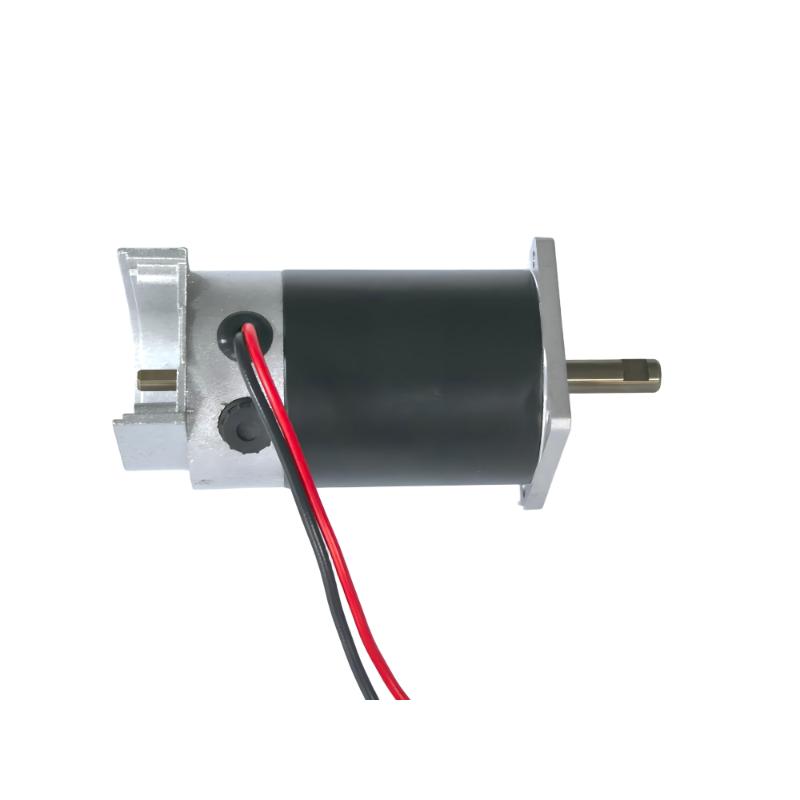
Mechanical commutation works via brushes and commutators, physically switching the current direction in the armature windings. The high torque brushed DC motor is ideal for intermittent duty cycles, cost-sensitive automation, and environments where simple two-wire control is preferred. However, limitations include brush wear, carbon dust generation, and unsuitability for explosive or clean-room environments due to arcing. You apply positive and negative voltage, and the shaft turns. Swap the wires, and it reverses. You do not need a complex electronic drive; a simple relay or contactor can handle basic operations. This makes them perfect for auxiliary mechanisms like automated clamps, simple diverters, or motorized doors. We specify these when the motor only runs for a few seconds at a time. The brushes will last for years under intermittent use. The initial hardware cost is incredibly low, freeing up budget for more critical system components.
Electronic commutation utilizes Hall effect sensors or sensorless back-EMF to switch current in the stator windings. The industrial brushless DC motor is perfect for continuous duty operations, high-speed automation, AI-driven precision robotics, and feedback-dependent positioning loops. Its value proposition includes superior thermal dissipation (heat generated at the stator, not the rotor), higher power density, and frictionless operation, leading to significantly longer lifespans. Because the windings are on the outside (the stator) and the permanent magnets are on the spinning rotor, heat escapes easily into the motor housing. You can push these motors much harder without melting the internal insulation. The lack of physical brushes means there is no arcing and no carbon dust. We use these exclusively in cleanrooms and semiconductor manufacturing. The only wearing parts are the bearings. If you size the motor correctly and keep it within its thermal limits, a brushless unit will run continuously for tens of thousands of hours without degradation.
A specific footprint, like the 50mm BLDC motor, solves spatial constraints in collaborative robots (cobots), AGV steering columns, and medical automation. It balances high torque output with a compact envelope, allowing for high power density in space-constrained applications without sacrificing thermal efficiency. This miniaturization enables more compact and agile automated systems. When designing a surgical robot, every millimeter matters. You need motors that fit inside slender robotic arms but still provide enough torque to manipulate tools with absolute rigidity. We achieve this by using high-grade neodymium magnets and concentrated winding techniques. These 50mm units often incorporate integrated planetary gearheads and high-resolution encoders directly into the housing. This creates a complete, drop-in motion axis that requires minimal external hardware. You bolt it in, connect the power and communication cables, and you have a fully functional, highly precise robotic joint.
Direct current systems provide dynamic response, making them ideal for positioning, robotic arms, and high-frequency start-stop cycles. They offer precise control over acceleration and deceleration. AC motors, conversely, provide constant-speed reliability, making them ideal for pumps, large fans, and continuous conveyors where dynamic response is less critical. The choice depends on whether the application requires precise motion control or steady, continuous operation. If you are pumping water into a holding tank, an AC induction motor is the correct choice. You turn it on, it runs at a fixed speed, and you turn it off when the tank is full. But if you are operating a pick-and-place machine that must grab a microchip, move it 300 millimeters, and place it on a circuit board within a tolerance of 10 microns, an AC motor will fail. You need the rigid, instantaneous control that only a direct current servo system can provide.
Direct current drive systems are straightforward, requiring basic PWM or analog control for speed and torque adjustment. This simplicity reduces controller costs and programming time. AC variable frequency drives (VFDs) require complex vector control algorithms for dynamic operations, increasing system complexity and cost. While VFD technology has advanced, direct current control remains inherently simpler for high-precision tasks. A PWM drive simply chops the voltage into pulses. Wider pulses mean more power; narrower pulses mean less power. The motor physically integrates these pulses into smooth rotation. An AC vector drive must constantly calculate the exact position of the rotor's magnetic field and inject precise currents into three separate phases to maintain control. This requires powerful microprocessors and complex tuning parameters. When you need to commission fifty axes of motion on a single machine, the simpler tuning of direct current drives saves days of engineering time.
Feature | Direct Current (Brushed/Brushless) | AC Induction |
|---|---|---|
Starting Torque | Extremely High (Maximum at zero speed) | Moderate to Low (Requires VFD for boost) |
Speed Control | Simple PWM or Voltage adjustment | Requires complex VFD (Frequency adjustment) |
Dynamic Response | Instantaneous (Ideal for servos) | Sluggish (High rotor inertia) |
Maintenance | Brushed: High / Brushless: Low | Very Low (Bearings only) |
Ideal Application | Robotics, AGVs, Precision Positioning | Pumps, Fans, Continuous Conveyors |
Integrating direct current power supplies and digital controllers within existing AC-dominant plant infrastructures requires careful planning. While AC power is ubiquitous, converting it to the precise voltage required adds components to the system. However, modern drives often include built-in rectification, simplifying integration. Engineers must ensure the power supply can handle the peak current demands during acceleration. When a heavy AGV accelerates, it pulls a massive current spike. If your power supply is undersized, the voltage will drop, causing the drive to fault out and stop the vehicle. We mitigate this by using shared DC bus architectures. Multiple motor drives connect to a single, large power supply. When one motor decelerates, it acts as a generator, pushing power back onto the bus. Another motor that is accelerating can consume this regenerated power. This reduces the total load on the main facility power grid and increases overall system efficiency.
AC induction motors are generally maintenance-free due to the lack of brushes. Brushed variants require periodic brush replacement and commutator cleaning. Brushless units bridge this gap, offering the maintenance-free operation of AC motors with the precision control of direct current, despite higher initial drive controller costs. Evaluating the long-term maintenance requirements is crucial for minimizing downtime in automated systems. You must schedule downtime to inspect brushes. If a brush wears down completely, the spring will score the commutator, destroying the motor. We implement strict preventative maintenance schedules based on operating hours. For critical, inaccessible machinery, we always specify brushless units. The higher upfront cost of the electronic drive is easily justified when you eliminate the need to send a technician into a hazardous area every six months to perform routine motor maintenance.
High-torque, low-speed applications risk overheating the motor due to reduced airflow from internal cooling fans. Mitigation involves proper sizing to ensure the motor operates within its thermal limits. Implementing active cooling, such as external blowers or liquid cooling, can manage excess heat. Strict adherence to duty cycle limits prevents thermal overload during intermittent operations. A motor running at 10% of its rated speed generates very little internal airflow. If it is simultaneously pushing maximum torque, the copper windings will heat up rapidly. We install thermistors directly into the stator windings. These sensors wire back to the drive amplifier. If the winding temperature exceeds a safe threshold, the drive automatically reduces the current limit or shuts down the system entirely. This thermal protection prevents catastrophic insulation failure and extends the operational life of the hardware.
For brushed variants, vibration increases brush arcing and accelerates wear, reducing lifespan. Mitigation requires establishing preventative maintenance schedules for regular inspection and replacement. Selecting motors with robust brush holder designs and high-quality brush materials can improve durability. In extreme vibration environments, transitioning to a brushless architecture is often the most reliable solution. When a machine vibrates heavily, the brushes bounce off the commutator. Every time contact breaks, an electrical arc forms. This arcing erodes both the brush and the copper commutator bars. We combat this by specifying constant-force brush springs that maintain even pressure regardless of brush length. We also use specific carbon-graphite compounds designed for high-vibration duty. However, if the vibration exceeds 5G, we abandon brushed technology entirely and redesign the axis to accommodate a brushless motor.
Electromagnetic interference (EMI) is generated by mechanical commutation or high-frequency switching. This EMI can disrupt sensitive control electronics and sensors. Mitigation involves using shielded cabling for motor power and feedback signals. Proper grounding of all system components is essential. Selecting industrial-grade motor controllers with built-in EMI filters minimizes interference and ensures stable system operation. A PWM drive switches hundreds of volts on and off thousands of times per second. This creates massive electrical noise. If you run an unshielded motor cable next to a low-voltage analog sensor wire, the noise will couple into the sensor circuit, causing erratic machine behavior. We mandate continuous, 360-degree shield terminations at both the drive and the motor housing. We separate power and signal cables into different physical conduits. We install ferrite chokes on the power lines to absorb high-frequency transients before they can radiate into the factory environment.
Map your exact load profiles, including peak starting torque and continuous operating torque, to ensure accurate motor sizing.
Consult manufacturer torque-speed curves to verify the selected motor meets the dynamic requirements of your application.
Evaluate digital drive controller compatibility to ensure seamless integration with your existing PLC or automation network.
Implement strict thermal monitoring and active cooling strategies for axes operating at low speeds and high loads.
Request prototype units for physical testing under real-world conditions before finalizing the specification.
A: They offer maximum torque at zero speed, essential for moving heavy loads from a standstill, and provide precise speed and positioning control required for accurate movement.
A: A BLDC motor uses electronic commutation for precise speed and torque control, while a standard AC motor relies on the frequency of the AC supply, typically offering less dynamic control without a complex VFD.
A: Speed is controlled by varying the voltage applied to the armature using Pulse Width Modulation (PWM) or by adjusting the field flux in the stator.
A: Armature voltage control adjusts speed below the base speed while maintaining constant torque. Field flux control adjusts speed above the base speed while maintaining constant horsepower.
A: Choose a brushed motor for cost-sensitive, intermittent-duty applications where simple control is preferred and routine maintenance like brush replacement is acceptable.
A: They utilize high-strength rare-earth magnets and optimized winding designs to maximize power density, delivering significant torque within a small spatial footprint.