close
Choose Your Site
Global
Social Media
Views: 0 Author: Site Editor Publish Time: 2026-09-28 Origin: Site
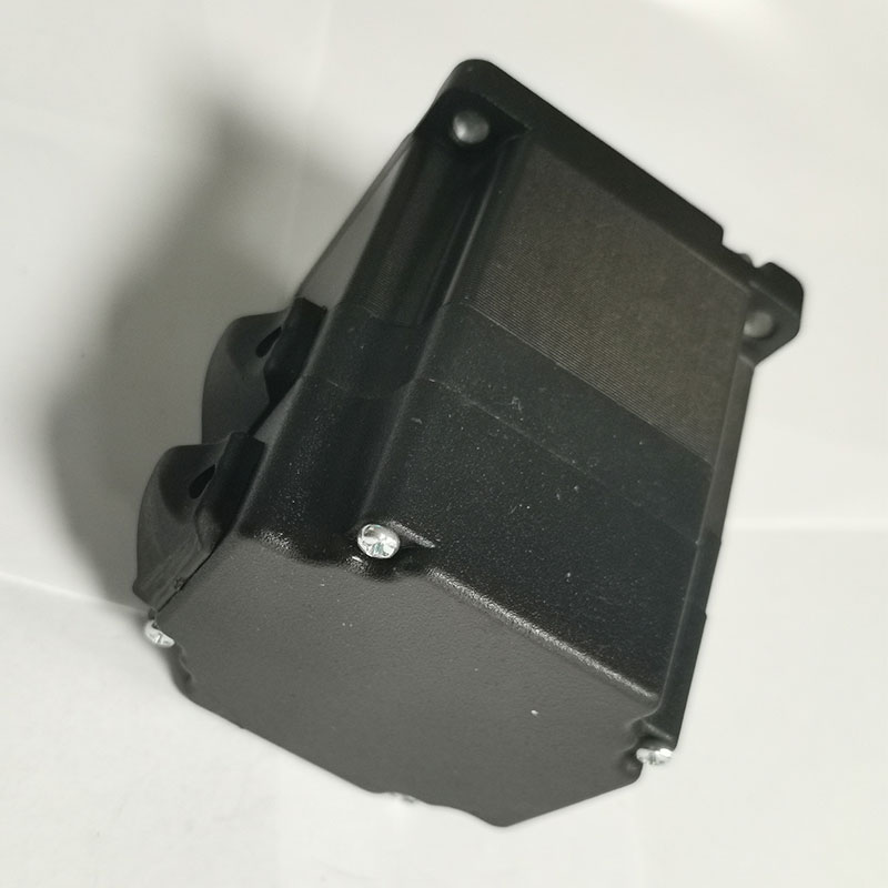
Replacing mechanical brushes with electronic commutation fundamentally changes how we design automated systems. A Brushless DC Motor eliminates physical wear, friction, and electrical arcing by utilizing a stationary stator and a rotating permanent magnet rotor. Specifying the correct motor for an equipment build requires moving past basic datasheet numbers. You must evaluate thermal limits, controller compatibility, and physical dimensions to ensure system reliability on the factory floor. This guide breaks down the internal mechanics of brushless architectures. We translate operational theory into practical evaluation criteria for your next project. You will learn sizing principles, manufacturing quality standards, and system integration techniques necessary for successful deployment. We focus on real-world engineering constraints, helping you match the right frame size and winding configuration to your specific load profile without over-engineering the solution.
Electronic Commutation Replaces Mechanical Wear: By moving electromagnets to the stator and permanent magnets to the rotor, BLDC motors eliminate sliding contacts and brush friction, drastically increasing operational lifespan and reducing maintenance.
Control Complexity is the Primary Trade-off: The absence of physical brushes requires an Electronic Speed Controller (ESC) or servo drive to sequence the current, shifting complexity from mechanical hardware to electronic software.
Manufacturing Techniques Dictate Reliability: Advanced assembly methods, such as bonding a brushless DC motor's permanent magnets, are critical for preventing rotor failure under high-RPM or high-temperature conditions.
Form Factor Determines Thermal and Torque Limits: Selecting between standard frame sizes (e.g., an 80mm brushless DC motor vs. a 90mm brushless DC motor) directly impacts heat dissipation capabilities and continuous torque output.
To evaluate a motor's suitability for a specific load, engineers must first understand internal magnetic field generation. You need to know how these fields are manipulated within the housing. This knowledge directly informs drive selection and mechanical integration.
The architecture inverts traditional motor design. Permanent magnets reside on the rotating armature, known as the rotor. Copper windings remain fixed to the exterior housing, called the stator. This physical arrangement dictates how the motor generates rotational force. The stator contains multiple electromagnetic poles constructed from stacked silicon steel laminations. These thin laminations prevent eddy currents from generating excess heat. When energized, the copper windings around these poles generate a rotating magnetic field in space. The permanent magnets on the rotor chase this rotating field, creating continuous mechanical rotation.
Pole count significantly impacts torque density and rotational smoothness. A higher pole count increases torque output at lower speeds and reduces cogging torque. Cogging torque is the jerky, pulsating movement felt when turning an unpowered motor by hand. It occurs because the permanent magnets naturally align with the iron teeth of the stator. Minimizing cogging torque is mandatory for precision robotics and smooth low-speed operation. Engineers often specify fractional slot winding configurations or skew the stator teeth to mitigate this effect.
Engineers must differentiate between stator winding configurations. The two primary types are Wye (Star) and Delta. Each offers distinct electrical characteristics for different load profiles.
Wye (Star) Windings: All three phases connect at a central neutral point. This configuration delivers high torque at low speeds. It requires less current to start and provides a very smooth torque ripple.
Delta Windings: The phases connect in a closed triangle. This setup provides higher top-end speeds. It sacrifices some low-end torque for maximum RPM, making it ideal for fans and pumps.
Hybrid Configurations: Advanced drives switch between Wye and Delta dynamically using external contactors. They optimize efficiency across the entire speed range, providing high starting torque and high top speed.
Commutation is the process of switching current in the stator windings to maintain a perpendicular magnetic field relative to the rotor. In older designs, physical carbon brushes handled this switching by dragging against a commutator ring. Brushless designs eliminate this mechanical contact entirely, relying on solid-state electronics.
An Electronic Speed Controller (ESC) manages the commutation. The ESC acts as the brain of the system. It converts the direct current (DC) power supply into an alternating, phased sequence. This sequence drives the electromagnets in a precise order. The controller must know the exact position of the rotor to time the current pulses correctly. If the timing is off, the motor stalls, stutters, or runs highly inefficiently, generating massive amounts of heat.
Controllers determine rotor position using two primary methods, each suited to different operational environments:
Sensored Commutation: This method uses physical Hall-effect sensors embedded in the stator slots. The sensors detect the magnetic field of the passing rotor magnets and send real-time position data to the ESC. Sensored setups excel at low speeds. They provide massive starting torque and prevent stuttering under heavy loads. They are standard in traction drives and robotic joints.
Sensorless Commutation: This approach eliminates physical sensors. The ESC detects Back-Electromotive Force (Back-EMF). As the rotor spins, the permanent magnets generate a small voltage in the unpowered stator coils. The controller reads this Back-EMF to calculate rotor position. Sensorless systems are highly robust because they lack fragile sensor wires. However, they struggle at zero speed. The rotor must be moving to generate Back-EMF.
Rotor Alignment: The controller injects a known DC current into two phases to force the rotor into a known, fixed starting position.
Open-Loop Ramp: The drive blindly steps the magnetic field forward at an increasing frequency to get the rotor spinning without position feedback.
Back-EMF Detection: Once the rotor reaches a minimum speed threshold, the un-driven phase generates enough voltage for the controller's analog-to-digital converters to read.
Closed-Loop Switch: The controller transitions to reading the Back-EMF signals for precise, real-time commutation timing.
Mechanical design translates directly into measurable performance metrics. OEM applications demand strict adherence to thermal, efficiency, and safety standards. Understanding these advantages helps engineers match the motor to the environmental constraints of the deployment site.
Heat degrades insulation and weakens permanent magnets. Brushless designs excel at thermal management. Placing the copper windings on the stationary exterior stator improves heat dissipation. The stator is in direct contact with the outer aluminum housing. Heat transfers easily to the environment through conduction and convection. In contrast, brushed motors trap heat on the inner rotor. The heat must cross an air gap to escape, which severely limits continuous power ratings.
Efficiency curves for these motors typically exceed 85 to 90 percent. The lack of physical friction from sliding brushes reduces energy waste. The motor converts more electrical power into mechanical work. This high efficiency extends battery life in mobile applications and reduces the electrical load on industrial power grids. Engineers maximize this efficiency by specifying high-grade neodymium magnets and minimizing the air gap between the rotor and stator.
The elimination of sliding contacts prevents electrical arcing. Arcing creates sparks and generates ozone. Spark-free operation makes the motor ideal for cleanrooms. It is mandatory for hazardous, explosive environments like chemical plants, grain elevators, or underground mining operations. Furthermore, there is no carbon dust. Brushed motors constantly shed conductive carbon dust as the brushes wear down. This dust contaminates sensitive electronics, fouls optical sensors, and requires regular internal cleaning.
These motors exhibit highly linear speed-torque characteristics. As load increases, speed drops predictably. This linearity simplifies control algorithms. Engineers can map performance curves with high accuracy. The motor delivers peak torque instantly from zero RPM. This characteristic is vital for traction applications, heavy lifting, and direct-drive extruders.
Precise speed regulation requires closed-loop control systems. The controller uses Pulse Width Modulation (PWM) to regulate power. PWM rapidly turns the voltage on and off across the switching transistors (MOSFETs or IGBTs). The ratio of "on" time to "off" time determines the average voltage sent to the motor. High-frequency PWM (typically 16kHz to 20kHz) ensures smooth rotation and pushes electrical noise above the range of human hearing. When paired with high-resolution optical encoders, the system achieves servo-level positioning accuracy. Dynamic response is exceptional. The low inertia of the rotor allows for rapid acceleration and deceleration profiles.
Matching physical dimensions to application requirements is a critical engineering phase. Standard industrial frame sizes dictate the performance envelope. You must balance space constraints against power demands, thermal mass, and bearing load capacities.
An 80mm brushless dc motor represents a sweet spot for many industrial designers. It offers a compact footprint while delivering substantial continuous torque. Typical wattage ranges from 200W to 750W, depending on the length of the stator stack. The 80mm frame is highly versatile and integrates easily into standard NEMA gearboxes.
Automated Guided Vehicles (AGVs) rely heavily on this size. Space within an AGV chassis is strictly limited. The motor must fit inside the wheel hub or adjacent to the transaxle. Mid-sized robotics and packaging machinery also utilize this form factor. The high power density allows for aggressive motion profiles without bulking up the machine design or increasing the moving mass of a gantry system.
The 80mm footprint has inherent thermal limitations. The surface area available for passive cooling is restricted. Pushing the motor to its peak torque rating for extended periods generates rapid heat buildup. If the application requires continuous operation near the thermal limit, active cooling becomes necessary. Engineers often integrate forced air fans, heat sinks, or liquid cooling jackets to maintain safe operating temperatures and protect the Class F winding insulation.
Sometimes the application demands more sustained power and higher radial load capacities. Scaling up to a 90mm brushless dc motor solves several engineering challenges. The primary advantage is the increased surface area. A larger exterior housing facilitates superior passive thermal dissipation. The motor sheds heat faster. This allows for higher continuous current ratings without triggering thermal shutdown or degrading the permanent magnets.
The physics of the larger diameter also improve performance. The larger rotor diameter increases the lever arm for magnetic flux. Torque is a product of force and distance. By moving the air gap further from the center shaft, the same magnetic force generates more rotational torque. You achieve higher continuous torque without necessarily increasing the RPM or drawing proportionally more current. The larger frame also accommodates heavier-duty bearings, extending the L10 bearing life under high radial or axial loads.
Target applications for the 90mm variant include heavy-duty traction drives and material handling carts. Industrial CNC spindles use them for rigid cutting operations where speed stability under varying loads is required. High-load conveyor systems benefit from the massive starting torque. When space permits, stepping up to a 90mm frame drastically improves system reliability and thermal headroom.
Specification Parameter | 80mm Frame Size | 90mm Frame Size |
|---|---|---|
Continuous Torque Capacity | Moderate (Best for mid-load applications) | High (Lever arm effect increases output) |
Thermal Dissipation | Limited surface area; may need active cooling | Excellent passive cooling via larger housing |
Rotor Inertia | Lower (Faster acceleration/deceleration) | Higher (Better speed stability under varying loads) |
Bearing Load Capacity | Standard radial and axial loads | High radial and axial load tolerance |
Typical Applications | AGVs, Packaging Machinery, Mid-sized Robotics | CNC Spindles, Heavy Conveyors, Traction Drives |
Addressing physical vulnerabilities is required for long-term reliability. Extreme operational stress exposes manufacturing weaknesses. The rotor assembly is particularly susceptible to failure under high RPMs and elevated temperatures. The method used to secure the magnets dictates the motor's survivability in harsh environments.
Securing permanent magnets to the rotor is a complex engineering challenge. Magnets can be surface-mounted (SPM) or inserted into the interior of the rotor lamination (IPM). Surface-mounted designs offer excellent torque but expose the magnets to massive centrifugal forces. As the rotor spins, these forces attempt to rip the magnets away from the steel core. The adhesive must resist this constant outward pull.
The process of assembling a bonding brushless dc motor relies on high-temperature, high-strength industrial adhesives. Manufacturers apply precise amounts of epoxy or acrylic-based structural adhesives to the rotor core. The magnets are placed using automated fixtures to ensure perfect alignment. The rotor then enters a curing oven to set the bond. This chemical retention must withstand decades of thermal cycling and mechanical shock.
Bonding presents significant engineering challenges. The most critical issue is matching the coefficient of thermal expansion. The neodymium magnet, the steel rotor, and the adhesive all expand at different rates when heated. If the mismatch is too great, the adhesive layer experiences severe shear stress. This stress causes micro-fractures in the glue line. Over time, these fractures propagate, leading to complete adhesive failure. Engineers specify toughened epoxies with high glass transition temperatures (Tg) to maintain flexibility and strength at 150 degrees Celsius.
Adhesive failure at high RPMs is catastrophic. If a magnet detaches, it instantly jams against the stator teeth. This destroys the motor, locks the shaft, and often damages the connected mechanical drivetrain. High temperatures also degrade adhesive strength. Standard epoxies soften and lose their shear strength when pushed past their thermal limits.
Engineers often compare adhesive bonding to mechanical retention methods. Mechanical retention includes wrapping the rotor in Kevlar, carbon fiber, or fiberglass tape. Some designs use a thin stainless steel or Inconel sleeve pressed over the magnets. Mechanical methods provide absolute security against centrifugal detachment. However, they increase the air gap between the rotor and stator. A larger air gap reduces magnetic flux density, which lowers overall motor efficiency and torque.
You must specify the retention method based on application severity. Standard industrial environments with moderate speeds rely safely on advanced bonding techniques. High-speed spindles, aerospace actuators, or motors subjected to extreme shock loads demand Kevlar wrapping or steel sleeving to guarantee structural integrity.
Balancing upfront complexities against long-term operational benefits defines the integration process. You cannot simply bolt the motor to a frame and apply power. The electronic infrastructure requires careful planning, wiring discipline, and software configuration.
Mismatched motors and controllers cause severe operational issues. A BLDC motor cannot run directly off a DC power supply. Connecting a battery directly to the phase wires will instantly short-circuit the system and melt the windings. You must use an ESC to manage the phase switching.
The ESC must match the motor's voltage and continuous current ratings. It must also support the correct commutation method. If the motor uses Hall sensors, the controller must have a corresponding sensor input port. The phase angles of the sensors (typically 60 or 120 degrees) must align with the controller's software settings. Incorrect sensor alignment causes the motor to draw massive current without generating any torque.
Engineering time is required for system tuning. You must configure the Proportional, Integral, and Derivative (PID) loops within the drive. Proper PID tuning prevents the motor from oscillating or overshooting its target position. You tune the Proportional gain for responsiveness, the Integral gain to eliminate steady-state error, and the Derivative gain to dampen oscillations. You also need to configure the PWM frequencies. A low PWM frequency causes audible motor whine and jerky movement. A high PWM frequency smooths rotation but increases heat generation within the controller's switching transistors.
Integrating the motor drive with higher-level systems takes careful planning. Motion controllers and Programmable Logic Controllers (PLCs) send commands to the ESC. This communication happens via analog signals (0-10V), step/direction pulses, or industrial fieldbus protocols like EtherCAT, PROFINET, or CANopen. Seamless integration ensures the motor responds instantly to system-level commands.
Wiring practices dictate signal integrity. The high-frequency switching of the ESC generates significant Electromagnetic Interference (EMI). You must use shielded cables for the motor phases and ground the shield at the drive end. Hall sensor wires must be twisted pairs to reject common-mode noise. Failure to implement proper grounding and shielding results in erratic motor behavior, false encoder counts, and communication dropouts on the fieldbus network.
Calculate your exact load profiles, including peak torque requirements during acceleration and continuous torque needs during steady-state operation.
Consult manufacturer torque-speed curves to verify the motor operates within its continuous duty zone for your specific application.
Evaluate form factor constraints early in the design phase to determine if an 80mm or 90mm frame provides the necessary thermal dissipation.
Verify the rotor manufacturing techniques by ensuring the magnet bonding process is rated for your expected temperature and RPM limits.
Engage with drive suppliers immediately to confirm ESC compatibility, sensor alignment, and fieldbus communication protocols before finalizing the motor specification.
A: The primary difference is the physical inversion of components. Brushless designs place permanent magnets on the rotor and electromagnets on the stator. They replace mechanical sliding contacts and carbon brushes with electronic commutation. This eliminates physical friction, reduces maintenance, and significantly extends the operational lifespan of the drive system.
A: No, it cannot. A brushless motor requires an Electronic Speed Controller (ESC) or servo drive. The controller converts the direct current (DC) supply into a sequenced alternating current to energize the stator phases in the correct order. Connecting DC power directly to the motor will cause a short circuit.
A: Bonding secures the permanent magnets to the rotating armature. High-strength industrial adhesives prevent the magnets from detaching under massive centrifugal forces and high temperatures. Proper bonding prevents catastrophic mechanical failure, ensuring the magnets do not strike the stator teeth during high-speed operation.
A: The choice depends on your physical space and power needs. An 80mm frame is ideal for tight spaces like AGVs and packaging machinery. A 90mm frame offers increased surface area for better thermal dissipation, higher continuous torque due to a larger rotor diameter, and heavier bearing load capacities.
A: The primary disadvantages include increased system complexity and the requirement for specialized electronic controllers. They demand precise PID tuning, proper EMI shielding, and integration knowledge that simple mechanical brushed motors do not need. The initial setup requires more engineering time and software configuration.
A: Sensorless control eliminates physical Hall-effect sensors. The controller reads the Back-Electromotive Force (Back-EMF) generated in the un-driven stator phases to determine the rotor's exact position. This method is highly reliable in harsh environments but struggles at zero speed, requiring an open-loop startup sequence.