
close
Choose Your Site
Global
Social Media

Views: 0 Author: Site Editor Publish Time: 2026-06-29 Origin: Site


Engineers frequently face a crossroads when specifying motion control components. While brushless technology dominates modern marketing headlines, the traditional brushed motor remains highly relevant. They serve as the most cost-effective and reliable choice for specific duty cycles and simple control systems. Many design teams overlook them, chasing trends instead of practical requirements. Selecting the wrong motor often leads to premature brush wear, severe thermal shutdown, or entirely unnecessary controller expenses. A mismatched drive system drains power and stalls critical operations. You need a reliable framework to evaluate your specific needs accurately. This guide provides a pragmatic, spec-driven approach to component selection. You will learn how to evaluate, size, and shortlist the exact Brushed Motor for your operational requirements. We focus on matching physical form factors to performance demands while mitigating common mechanical risks.
Base motor selection on continuous torque requirements, not just peak stall torque.
Physical footprint heavily dictates motor class (e.g., matching a 40mm, 57mm, or 63mm frame to the spatial envelope).
Brushed motors offer superior ROI in applications requiring simple variable speed control without complex electronics.
Real-world implementation requires proactive management of brush friction, thermal output, and Electromagnetic Interference (EMI).
Every successful engineering project begins with accurate performance baselines. You cannot select an appropriate drive system without mapping your physical loads. Establishing clear metrics prevents undersizing, which causes overheating. It also prevents oversizing, which wastes space and energy.
You must understand the inverse relationship between speed and torque. In standard DC designs, speed drops linearly as the mechanical load increases. Maximum speed occurs at zero torque, known as the no-load speed. Maximum torque occurs at zero speed, known as stall torque. You must define your continuous operating torque carefully. Do not base your selection solely on stall torque. If your application runs continuously near the stall limit, the windings will rapidly overheat. Identify the normal running load and ensure it falls within the motor's maximum efficiency zone. This zone typically sits around eighty percent of the no-load speed.
Matching the rated voltage to your available power supply is a non-negotiable step. Voltage strictly dictates the rotational speed. Current directly dictates the rotational torque. You must address the differences between battery-powered constraints and grid-tied systems. Battery systems experience voltage drops as they discharge. This drop reduces the maximum available speed over time. Grid-tied systems provide stable voltage, allowing for consistent high-speed operation. Always calculate the maximum current draw during stall conditions. Ensure your power supply and wiring can handle these sudden current spikes without tripping breakers or causing voltage sags.
You must differentiate between continuous operation and intermittent use. Continuous operation demands robust thermal management. The internal components constantly generate heat. Intermittent duty cycles allow the internal coils to cool down between operations. Traditional brushed designs excel in intermittent scenarios. Applications like power seats or retractable awnings operate for just a few seconds. The cooling periods prevent demagnetization and extend component life significantly. Profile your precise active and resting times before finalizing any specifications.
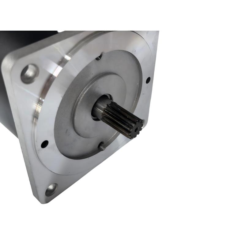
Physical size constraints dictate your final hardware choices more often than electrical limits. You must match the mechanical power requirements to the available spatial envelope. A motor might look perfect on paper but fail if it cannot physically fit inside your equipment housing.
Equipment housing directly dictates the maximum allowable diameter and length. A tightly sealed housing restricts airflow, limiting heat dissipation. Compact spatial envelopes force you to choose motors with higher power density. However, smaller frames cannot dissipate heat as effectively as larger frames. You must balance the physical dimensions against the required thermal limits. Review your CAD models early in the design phase. Leave adequate clearance for wiring terminals, rear shafts, and optional encoders.
Matching the precise diameter to your application prevents mechanical integration headaches. Manufacturers categorize their designs heavily by frame diameter. You should familiarize yourself with standard industry sizing tiers.
When you design compact robotics or portable medical devices, space is at an absolute premium. Weight reduction is critical for portable equipment. You should evaluate a 40mm mini DC motor for these scenarios. They fit perfectly into automated smart locks, handheld tools, and small surveillance pan-tilt mechanisms. They provide excellent responsiveness in a minimal footprint.
If you build office automation equipment, you need balanced torque-to-weight ratios. Medium-duty power tools and specialized linear actuators require similar balance. We recommend exploring a 57mm DC motor. This frame size serves as the definitive middle-ground. It provides enough surface area for decent cooling while remaining compact enough for tight enclosures.
High-load industrial environments demand rugged components. Conveyor systems, Automated Guided Vehicles (AGVs), and industrial winches push equipment to the limits. A 63mm brushed DC motor delivers exceptional performance here. The larger diameter accommodates heavier copper windings. This increases the continuous torque limits and improves thermal mass, allowing it to survive harsh stalling events.
Motor Frame Size Application Chart | |||
Motor Class | Primary Advantage | Common Applications | Duty Cycle Suitability |
|---|---|---|---|
40mm Frame | High space efficiency, low weight | Smart locks, medical pumps, robotics | Intermittent / Light Continuous |
57mm Frame | Balanced torque and thermal mass | Linear actuators, office automation | Mixed / Medium Continuous |
63mm Frame | Maximum torque, high durability | AGVs, heavy conveyors, winches | Heavy Continuous / High Peak Loads |
Many engineers blindly specify complex modern solutions when simpler technology suffices. You must justify your component choices based on actual project requirements. Traditional designs offer distinct advantages in integration simplicity and environmental resilience.
The primary advantage of older architectures is their simplified control requirement. They require a basic two-wire DC connection to operate. You do not need costly Electronic Speed Controllers (ESCs). You do not need complex commutation logic or hall-effect sensor feedback. Applying voltage spins the shaft. Reversing the polarity reverses the direction. You can control speed effortlessly using inexpensive Pulse Width Modulation (PWM) circuits. This simplicity accelerates prototyping and reduces software development timelines.
You must weigh lower upfront hardware costs against long-term maintenance realities. Traditional designs cost significantly less to manufacture and purchase. However, the physical brushes undergo mechanical wear over time. You will face maintenance intervals for brush replacement. The math favors this older technology in predictable intermittent duty applications. If the equipment only runs for ten minutes a day, the brushes will likely outlast the entire product lifecycle. In these scenarios, paying a premium for complex electronic drives yields zero return on investment.
Lack of sensitive onboard electronics provides a distinct durability advantage. Silicon chips and microcontrollers fail rapidly in high-radiation environments. They also suffer under extreme physical vibration. A purely mechanical commutation system resists these harsh conditions brilliantly. As long as you properly seal the outer enclosure against dust and moisture, the unit will operate reliably where advanced electronics would instantly fail.
You cannot deploy mechanical commutation without addressing its physical byproducts. Successful integration requires you to proactively manage thermal output, friction wear, and electrical noise.
Heat acts as the primary enemy of performance. Excessive heat degrades permanent magnet strength permanently. For example, standard Neodymium magnets lose their magnetic flux if pushed past their rated temperature limits. High temperatures also accelerate physical brush wear and degrade winding insulation. You must implement effective cooling strategies. Utilize external ventilation slots if the environment remains clean. In dirty environments, rely on extruded aluminum heat sinks attached directly to the motor housing. Ensure your equipment enclosure has a designated thermal path to channel heat away from the core.
Set realistic expectations for mechanical lifespan based on your selected materials. Operating load directly dictates how fast the brushes degrade. High current loads require dense carbon or copper-graphite brushes. These materials handle electrical spikes well but generate carbon dust. Low-current, high-precision applications benefit from precious metal brushes. Precious metals offer incredibly low electrical noise but will melt under high stall currents. Always match the brush material to your specific amperage requirements and acceptable maintenance schedules.
You must address the technical reality of arcing at the commutator. Every time the internal coils switch polarity, a tiny electrical arc forms. This arcing generates broad-spectrum Electromagnetic Interference (EMI). This noise disrupts nearby sensors, microcontrollers, and communication arrays. You must implement concrete solutions to meet EMC compliance standards. Solder ceramic capacitors directly across the power terminals to absorb high-frequency spikes. Install ferrite beads on the main power cables. Always use properly shielded cables, grounding the shield at the power supply end.
You need a repeatable process to filter through hundreds of vendor catalogs. Follow these sequential steps to shortlist the ideal component for your equipment safely.
Chart the Application Profile: Document your exact requirements before contacting any suppliers. Note the required operational RPM under load. Calculate the nominal continuous torque required to keep your mechanism moving. Clearly state your available voltage and maximum allowable current draw.
Define Environmental & Physical Limits: Determine the absolute maximum footprint available in your CAD assembly. Limit your search specifically to frames that fit. For example, strict dimensional limits might force you to restrict searches to 57mm frames only. Define your required Ingress Protection (IP) ratings based on environmental exposure to water or dust.
Analyze the Vendor's Torque-Speed Curve: Request technical data sheets. Do not look solely at the maximum output limits. Instruct your team to look for efficiency sweet spots. Locate the point on the curve where output power is highest while current draw remains moderate. Ensure your normal operating load falls squarely within this high-efficiency zone.
Request Prototypes for Destructive Testing: Never order high-volume production units based purely on paper specifications. Advise your procurement team to order several sample units. Subject these samples to destructive testing. Push them to thermal failure. Measure real-world EMI emissions inside your actual equipment housing. Validate the thermal management strategy before signing volume purchasing agreements.
Successful motion control design balances mechanical simplicity against strict physical size constraints. Traditional brushed components provide exceptional value and reliability when deployed in the correct operational contexts. You must prioritize continuous torque ratings over peak stall limits to prevent catastrophic thermal failures. By matching your spatial envelope to specific frame diameters, you guarantee seamless mechanical integration. Careful management of heat, wear, and electromagnetic interference ensures long-term operational stability. Encourage your engineering buyers to finalize their torque and speed charts immediately. Next, contact trusted OEM manufacturers to request detailed technical data sheets and order physical sample units for immediate prototype testing.
A: The number of wire turns on the armature dictates the performance tradeoff between speed and torque. Fewer turns (low T) result in lower resistance, producing higher RPM but lower torque and significantly higher current draw. More turns (high T) increase resistance, yielding much higher torque and better low-speed control, but drastically reduce the maximum top speed.
A: Lifespan typically ranges from 1,000 to over 3,000 continuous operating hours. This metric depends heavily on the specific brush material, operating voltage, and your applied duty cycle. Precious metal brushes last longer under light loads, while carbon brushes handle heavier currents but wear down mechanically faster due to friction.
A: Overvolting drastically increases both rotational speed and mechanical power output. However, it severely accelerates thermal failure. The excess voltage causes aggressive brush arcing at the commutator, pitting the copper contacts. This practice generates excessive heat, melts internal winding insulation, and drastically reduces the overall operational lifespan of the unit.


